PMSM Mechanical Parameter Estimator
Estimate back EMF constant, rotor inertia, and viscous damping of permanent magnet synchronous motor (PMSM)
Since R2023a
Libraries:
Motor Control Blockset /
Parameter Estimation /
PMSM Parameter Estimation
Description
The PMSM Mechanical Parameter Estimator block uses the phase currents and voltages, DC voltage across the motor, motor position and speed, stator resistance, d-axis inductance, as well as the other test configuration elements to compute the following mechanical parameters of a PMSM:
Back EMF constant (Ke)
Rotor inertia (J)
Viscous damping (B)
The block starts the motor using open-loop V by F or I-F control. You can use the Start up technique parameter to select one of these startup methods.
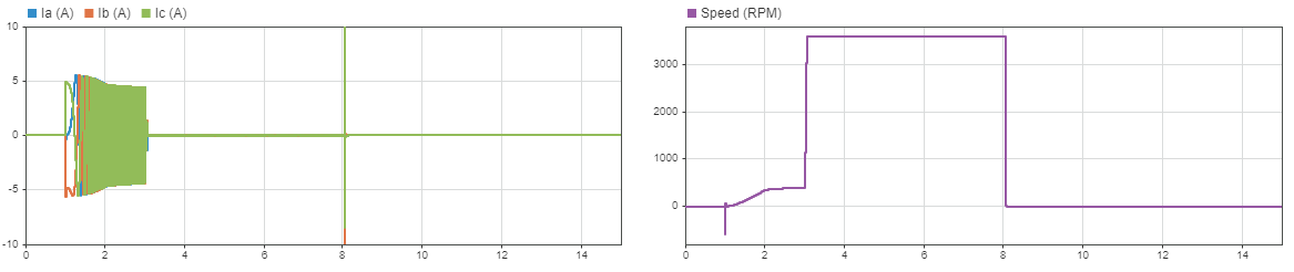
After starting the motor, the block runs the motor using closed-loop field-oriented control (FOC) with a limited speed. With the motor running, the block runs the tests to estimate the back-EMF constant (Ke) and viscous damping (B). After a pre-configured duration, the block concludes these tests to compute Ke and B. The block then triggers coast-down by shutting down all six inverter switches. The coast-down results in gradual decline in motor speed which eventually reaches zero. The block measures and uses the time to reach zero-speed to calculate rotor inertia (J).
Examples
Simulate PMSM Parameter Estimations
Use parameter estimation blocks to simulate PMSM resistance, inductance, and back EMF estimations.
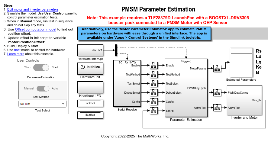
Estimate PMSM Parameters Using Parameter Estimation Blocks
Uses the parameter estimation blocks provided by Motor Control Blockset™ to estimate these parameters of a permanent magnet synchronous motor (PMSM) with a quadrature encoder sensor:
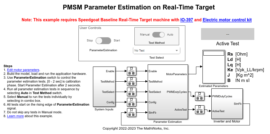
Estimate PMSM Parameters Using Parameter Estimation Blocks on Real-Time Systems
Uses the parameter estimation blocks provided by Motor Control Blockset™ to estimate these parameters of a permanent magnet synchronous motor (PMSM):