Main Content

Simplified Induction Motor

Induction motor powered by ideal AC supply

  • Simplified Induction Motor block

Libraries:
Simscape / Electrical / Electromechanical / Asynchronous

Description

The Simplified Induction Motor block represents the electrical and torque characteristics of an induction motor powered by an ideal AC supply. The following figure shows the equivalent circuit model of the Simplified Induction Motor block.
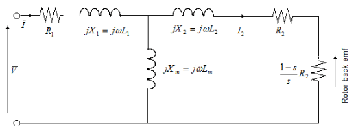
In the figure:

  • R1 is the stator resistance.

  • R2 is the rotor resistance with respect to the stator.

  • L1 is the stator inductance.

  • L2 is the rotor inductance with respect to the stator.

  • Lm is magnetizing inductance.

  • s is the rotor slip.

  • V¯ and I¯ are the sinusoidal supply voltage and current phasors.

Rotor slip s is defined in terms of the mechanical rotational speed ωm, the number of pole pairs p, and the electrical supply frequency ω by

s=1pωmω

This means that the slip is one when starting, and zero when running synchronously with the supply frequency.

For an n-phase induction motor the torque-speed relationship is given by:

T=npR2sωVrms2(R1+R2+1ssR2)2+(X1+X2)2

where:

  • Vrms is the line-neutral supply voltage for a star-configuration induction motor, and the line-to-line voltage for a delta-configuration induction motor.

  • n is the number of phases.

You can parameterize this block in terms of the preceding equivalent circuit model parameters or in terms of the motor ratings the block uses to derive these parameters.

This block produces a positive torque acting from the mechanical C to R ports.

Model Thermal Effects

You can expose thermal ports to model the effects of losses that convert power to heat. To expose the thermal ports, set the Modeling option parameter to either:

  • No thermal port — The block does not contain thermal ports.

  • Show thermal port — The block contains multiple thermal conserving ports.

For more information about using thermal ports in actuator blocks, see Simulating Thermal Effects in Rotational and Translational Actuators.

Assumptions and Limitations

  • The block does not model the starting mechanism for a single-phase induction motor.

  • When you parameterize the block by motor ratings, the block derives the equivalent circuit model parameters by assuming that the effect of the magnetizing inductance Lm is negligible, and the magnetizing inductance is not included in the simulated component.

Ports

Output

expand all

Physical signal port associated with the motor real power.

Physical signal port associated with the motor mechanical speed.

Physical signal port associated with the motor imaginary power.

Physical signal port associated with the motor slip.

Conserving

expand all

Mechanical rotational conserving port associated with the rotor.

Mechanical rotational conserving port associated with the motor case.

Stator thermal port.

Dependencies

To enable this port, set Modeling option to Show thermal port.

Rotor thermal port.

Dependencies

To enable this port, set Modeling option to Show thermal port.

Parameters

expand all

Whether to enable the thermal ports of the block and model the effects of losses that convert power to heat.

Electrical Torque

Select one of the following methods for block parameterization:

  • By motor ratings — Provide electrical torque parameters that the block converts to an equivalent circuit model of the motor assuming that the effect of the magnetizing inductance Lm is negligible.

  • By equivalent circuit parameters — Provide electrical parameters for an equivalent circuit model of the motor.

Resistance of the stator winding. The default value is 1 Ω.

Dependencies

This parameter is visible only when you set the Model parameterization parameter to By equivalent circuit parameters.

Resistance of the rotor, specified with respect to the stator.

Dependencies

This parameter is visible only when you set the Model parameterization parameter to By equivalent circuit parameters.

Inductance of the stator winding.

Dependencies

This parameter is visible only when you set the Model parameterization parameter to By equivalent circuit parameters.

Inductance of the rotor, specified with respect to the stator.

Dependencies

This parameter is visible only when you set the Model parameterization parameter to By equivalent circuit parameters.

Magnetizing inductance of the stator. Its value is hard to estimate from motor parameters, but the effect is usually small. If you do not know its value, use a typical value of 25 times the Stator inductance L1 value.

Dependencies

This parameter is visible only when you set the Model parameterization parameter to By equivalent circuit parameters.

Mechanical power the motor delivers when running at the rated speed.

Dependencies

This parameter is visible only when you set the Model parameterization parameter to By motor ratings.

Speed at which the motor delivers the specified Rated mechanical power value.

Dependencies

This parameter is visible only when you set the Model parameterization parameter to By motor ratings.

Line-to-line voltage at which the motor ratings are specified.

Dependencies

This parameter is visible only when you set the Model parameterization parameter to By motor ratings.

Frequency of the AC supply voltage at which the motor ratings are specified.

Dependencies

This parameter is visible only when you set the Model parameterization parameter to By motor ratings.

Line current at which the motor delivers the specified Rated mechanical power value.

Dependencies

This parameter is visible only when you set the Model parameterization parameter to By motor ratings.

Select one of the following parameterizations for the equivalent circuit resistance, R1, of the motor:

  • From motor efficiency — Calculate R1 from the motor efficiency. This is the default method.

  • From power factor — Calculate R1 from the motor power factor.

  • Use measured stator resistance R1 — Measure R1 directly.

Dependencies

This parameter is visible only when you set the Model parameterization parameter to By motor ratings.

The percentage of input power to the motor that gets delivered to the mechanical load when running at the Rated speed value.

Dependencies

This parameter is visible only when you set the Model parameterization parameter to By motor ratings and the R1 parameterization parameter to From motor efficiency.

The cosine of the angle by which the supply current lags the supply voltage when running at the Rated mechanical power value.

Dependencies

This parameter is visible only when you set the Model parameterization parameter to By motor ratings and the R1 parameterization parameter to From power factor.

The measured stator resistance.

Dependencies

This parameter is visible only when you set the Model parameterization parameter to By motor ratings and the R1 parameterization parameter to Use measured stator resistance R1.

Total number of pole pairs for the motor.

Number of supply phases.

Select one of the following motor configurations:

  • Delta configuration — Connect the motor stator windings in delta configuration.

  • Star configuration — Connect the motor stator windings in star configuration.

Power Supply

The line-to-line voltage that supplies the motor.

Frequency of the AC supply voltage.

Mechanical

Rotor inertia. The value can be zero.

Rotor damping. The value can be zero.

Speed of the rotor at the start of the simulation.

Temperature Dependence

This tab appears only for blocks with exposed thermal ports.

A 1 by 2 row vector defining the coefficient α in the equation relating resistance to temperature, as described in Thermal Model for Actuator Blocks. The first element corresponds to the stator, and the second to rotor. The default value is for copper.

The temperature for which motor parameters are defined.

Thermal Port

This tab appears only for blocks with exposed thermal ports.

A 1 by 2 row vector defining the thermal mass for the stator and rotor windings. The thermal mass is the energy required to raise the temperature by one degree.

A 1 by 2 row vector defining the temperature of the stator and rotor thermal ports at the start of simulation.

References

[1] S.E. Lyshevski. Electromechanical Systems, Electric Machines, and Applied Mechatronics, CRC, 1999.

Extended Capabilities

C/C++ Code Generation
Generate C and C++ code using Simulink® Coder™.

Version History

Introduced in R2008a