convertVibration
Compute baseline-corrected and filtered acceleration, velocity, and displacement signals from vibration measurements using a single sensor output from either an accelerometer, velocity sensor, or displacement sensor
Since R2024a
Syntax
Description
The convertVibration function converts accelerometer signals
into baseline-corrected and filtered velocity and displacement signals. This function is
especially useful when you plan to perform machine vibration monitoring using ISO 10816 and
20816
vibration standards. You can also use convertVibration to convert
displacement or velocity measurements into the three signal forms.
The ISO standards are provided for RMS velocity measurements (in mm/s) and displacement
measurements (in μm), but not for accelerometer measurements (in g or
mm/s2). convertVibration uses a combination
of high-pass filtering, integration, and baseline correction to accurately convert
accelerometer measurements into both velocity and displacement signals. The function uses a
similar algorithm to convert position signals to acceleration, but with differentiation
instead of integration. Converting velocity signals to acceleration and position uses a
combination of differentiation and integration.
The units in the convertVibration output signals are consistent with
the units of the input signals and the integration or differentiation functions that the
function performs.
Integration (such as acceleration to velocity): Input-signal unit is multiplied by seconds, so, for example, m/s2 becomes m/s.
Differentiation: (such as displacement to velocity): Input-signal unit is divided by seconds, so, for example, m becomes m/s.
If the input is in units of g, you must multiply the output by 9.81 to convert the results to m/s (velocity) or m (displacement).
Return Converted Signals
[___] = convertVibration(___,
allows you to specify additional parameters using one or more name-value arguments. For
example, if your data in Name=Value)T represents a velocity signal rather than
an acceleration signal, use the name-value argument
Type="velocity".
[___,
also returns the Options] = convertVibration(___)Options structure containing various parameter values
that the software used to perform the conversion, such as sampling frequency
Fs and lowpass filter cutoff frequency
Fmax.
You can use this syntax with any of the previous input and output argument combinations.
Plot Converted Signals
convertVibration(___) plots the converted
signals.
Examples
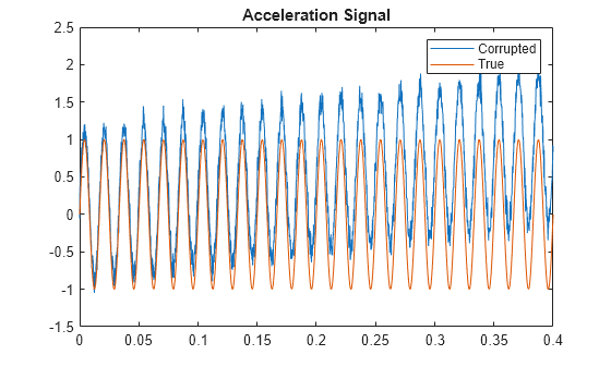
Load the data, which consists of a true acceleration signal acc_true, the measured acceleration acc_meas, which includes noise, offset, and drift, and the sampling frequency Fs.
load acceldata acc_meas acc_true Fs
Generate a time vector from Fs.
t = (0:1/Fs:0.4);
Plot the true and corrupted signals together.
plot(t,acc_meas,t,acc_true)
title('Acceleration Signal')
legend('Corrupted','True')
Use convertVibration to apply baseline correction to the accelerometer signal, and convert the signal into velocity and displacement signals. Use the syntax that plots all three signals.
convertVibration(acc_meas, Fs);
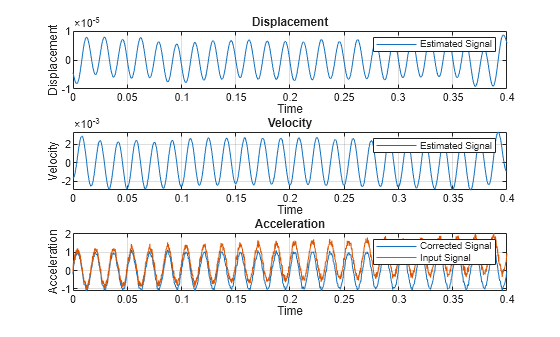
The conversion corrects the acceleration signal and produces stable displacement and velocity signals.
Save the signals by specifying output arguments.
[A,V,D] = convertVibration(acc_meas,Fs);
Load the data, which consists of a true velocity signal vel_true, the measured velocity vel_meas, which includes noise, offset, and drift, and the sampling frequency Fs. The signals are stored in timetables.
load veldata vel_meas_tt vel_true_tt Fs
Generate a time vector from Fs.
t = (0:1/Fs:0.2)';
Plot the true and corrupted signals together.
plot(t,vel_meas_tt.vel,t,vel_true_tt.vel)
title('Velocity Signal')
legend('Corrupted','True');

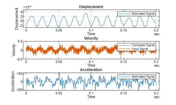
Use convertVibration to apply baseline correction to the velocity signal, convert and correct the acceleration and displacement signals, and return all three signals. Set the cutoff frequency Fmax to 500 to reduce the effect of high-frequency noise. Return all three signal types as well as information on the options used.
[a,v,d,options] = convertVibration(vel_meas_tt,Var="vel",Type="velocity",FMax=500);
Examine the options you used.
options
options = struct with fields:
        Fmin: 20
        Fmax: 500
        Type: "velocity"
    Variable: "vel"
          Fs: 10000
options contains information on the frequency range, the signal type, the variable name, and the sampling frequency.
Plot the three signals.
convertVibration(vel_meas_tt,Var="vel",Type="velocity",FMax=500);
Compare the corrected velocity with the true velocity.
figure
plot(t,v,t,vel_true_tt.vel)
legend('Corrected Velocity','True Velocity')

The corrected velocity has a much better fit than the measured velocity to the true velocity.
Input Arguments
Name-Value Arguments
Output Arguments
Algorithms
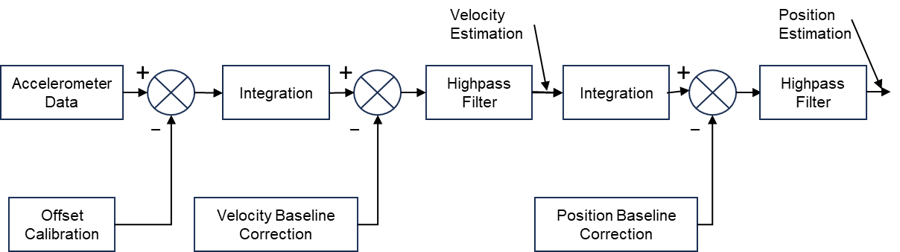
The convertVibration algorithm is based on the numerical integrator
design described in [1]. The
integrator contains three stages, each stage of which includes some combination and sequence
of offset or baseline calibration, highpass filtering, and integration. The result is a stable
velocity signal and displacement signal. The following block diagram, adapted from [1],
illustrates the general algorithm flow for an accelerometer input.
A similar algorithm converts position data to the three corrected outputs, but uses
differentiation instead of integration. For converting velocity data,
convertVibration uses a combination of integration and
differentiation.
References
[1] S. Thenozhi, W. Yu and R. Garrido, "A novel numerical integrator for structural health monitoring." 2012 5th International Symposium on Resilient Control Systems, Salt Lake City, UT, USA, 2012, pp. 92-97, doi: 10.1109/ISRCS.2012.6309300.
Version History
Introduced in R2024a