interplexmod
Description
[
modulates the input signals modsignal,efficiency] = interplexmod(signal,ampfactor)signal and returns an interplexed signal
modsignal and the power efficiency of the interplexing process
efficiency. The amplification factor ampfactor
defines the power distribution between the signals.
For more information, see Interplex Modulation Workflow.
Examples
Generate four random signals to modulate.
numSignals = 4;
x = 2*randi([0 1],1000,numSignals) - 1;
Set the power distribution among the signals to 20%, 20%, 40%, and 20%, respectively.
Calculate the corresponding amplitude factors as the square root of the power distribution of that signal.
ampfactor = [sqrt(0.2) sqrt(0.2) sqrt(0.4) sqrt(0.2)];
Apply interplex modulation to the four signals.
[y,efficiency] = interplexmod(x,ampfactor);
Display the power efficiency of interplexing process.
disp(efficiency)
0.4167
Perform interplex modulation on these three Navigation with Indian Constellation (NavIC) signals to generate a complex baseband waveform.
Standard Positioning Service (SPS) signal
Restricted Service (RS) data signal
RS-pilot signal
Set the pseudo-random number (PRN) index for the satellite.
PRNID = 1;
Set the number of navigation data bits in the generated waveform.
numNavDataBits = 3;
NavIC uses course acquisition codes (C/A-codes) for spreading the navigation data spectrum at a chipping rate of 1.023 Mcps.
numCAChipsPerDataBit = 1023*20;
randNavICData = 1 - 2*randi([0 1],1,numNavDataBits);
caCode = 1 - 2*double(gnssCACode(PRNID,"NavIC L5-SPS"));

% Each navigation data bit corresponds to 20 repetitions of C/A-code
caBits = repmat(caCode,20,1);
SPSsig = caBits.*randNavICData; % Spread SPS data
Generate random data bits for RS-pilot and RS-data signals.
dummyRSP = randi([0 1],numCAChipsPerDataBit*numNavDataBits,1); % RS pilot signal
dummyRSD = randi([0 1],numCAChipsPerDataBit*numNavDataBits,1); % RS data signal
Modulate the RS signals by using binary offset carrier (BOC) modulation. Rate-match the SPS signals with the BOC-modulated RS signals.
RSPsig = bocmod(dummyRSP,5,2);
RSDsig = bocmod(dummyRSD,5,2);
RateMatchedSPSsig = repelem(SPSsig(:),10,1);
Set the amplification factors for the RS-data, SPS, and RS-pilot signals, in that order.
ampfactors = [2/3 sqrt(2)/3 sqrt(2)/3];
Perform interplex modulation of SPS, RS-pilot, and RS-data signals.
[NavICBBWaveform,efficiency] = interplexmod([RSDsig,RateMatchedSPSsig,RSPsig],ampfactors);
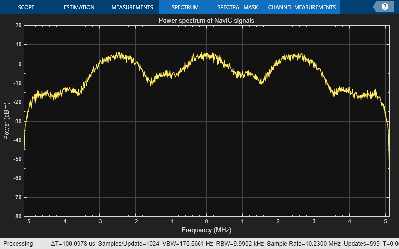
Visualize the complex NavIC baseband waveform.
fs = 10*1.023e6;                               % Sample rate
bbscope = spectrumAnalyzer(SampleRate=fs, ...
     Title="Power spectrum of NavIC signals");
bbscope(NavICBBWaveform)
Perform interplex modulation on these three Global Positioning System (GPS) signals to generate a complex baseband waveform.
C/A-code
L1 civil (L1C) data ranging code (L1CD)
M-code
Set the PRN index for the satellite.
PRNID = 1;
Set the number of C/A-code navigation data bits in the generated waveform.
numNavDataBits = 1;
Initialize random data for each GPS signal.
randLNAVData = randi([0 1],1,numNavDataBits);
% L1CD data bits are twice of C/A-code for same time duration
randCNAV2Data = randi([0 1],1,2*numNavDataBits);
Generate a C/A-code for the set PRNID.
caCode = gnssCACode(PRNID,"GPS");
tempCABits = repmat(caCode,20,1);
caBits = xor(tempCABits,randLNAVData);
rateMatchedCABits = repelem(caBits(:),40); % Rate match with M-code signal
caCodeSig = 1 - 2*rateMatchedCABits(:);
Generate L1C-codes for the set PRNID.
l1cd = gpsL1CCodes(PRNID);
licdBits = xor(l1cd,randCNAV2Data);
l1cdSig = -1*bocmod(licdBits(:),1,1,20);
The spreading code rate for the M-code is 5.115 Mcps, and one bit duration is 20 ms.
numChipsPerDataBit = (5*1023)*20;
Generate random data bits as M-coded data, and then modulate the bits using BOC modulation.
mCode = randi([0,1],numChipsPerDataBit*numNavDataBits,1);
mCodeSig = bocmod(mCode,10,5);
Set the amplification factors for the C/A-code, L1CD, and M-code signals, in that order.
ampfactors = [sqrt(0.4) sqrt(0.1) sqrt(0.4)];
Perform interplex modulation of the three GPS signals.
[GPSL1BBWaveform,efficiency] = interplexmod([caCodeSig l1cdSig mCodeSig],ampfactors);
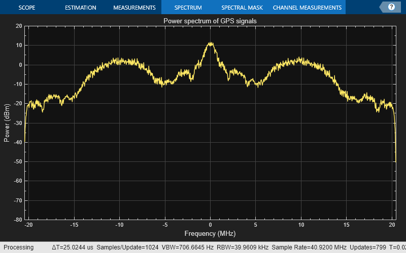
Visualize the complex GPS baseband waveform.
fs = 40*1.023e6;                              % Sample rate
bbscope = spectrumAnalyzer(SampleRate=fs, ...
      Title="Power spectrum of GPS signals");
bbscope(GPSL1BBWaveform)
Input Arguments
Output Arguments
More About
This block diagram helps to understand how multiple input signals are modulated by the
interplexmod function.
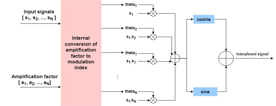
Here, thetaN represents the modulation index and is calculated internally using this formula:
where a represents the amplification factor.
References
[1] Butman, S. and Timor, U. Interplex - An efficient Multichannel PSK/PM Telemetry System. IEEE Transactions on Communications, 20(3), pp.415-419.
Extended Capabilities
Version History
Introduced in R2024a