Statistical Analysis in SerDes Systems
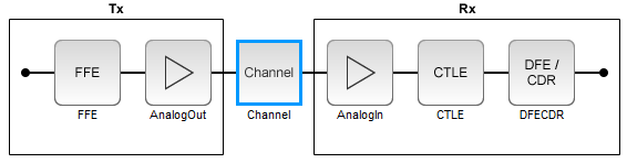
A SerDes system simulation involves a transmitter (Tx) and a receiver (Rx) connected by a passive analog channel. There are two distinct phases to a SerDes system simulation: statistical analysis and time-domain analysis. Statistical analysis (also known as analytical, linear time-invariant, or Init analysis) is based on impulse responses enabling fast analysis and adaptation of equalization algorithms. Time-domain analysis (also known as empirical, bit-by-bit or GetWave analysis) is a waveform-based implementation of equalization algorithms that can optionally include nonlinear effects.
The reference flow of statistical analysis differs from time-domain analysis. During a statistical analysis simulation, an impulse response is generated. The impulse response represents the combined response of the transmitter’s analog output, the channel, and the receiver’s analog front end. The impulse response of the channel is modified by the transmitter model's statistical functions. The modified impulse response from the transmitter output is then further modified by the receiver model's statistical functions. The simulation is then completed using the final modified impulse response which represents the behavior of both AMI models combined with the analog channel.

During a time-domain simulation, a digital stimulus waveform is passed to the transmitter model's time-domain function. This modified time-domain waveform is then convolved with the analog channel impulse response used in the statistical simulation. The output of this convolution is then passed to the receiver model's time-domain function. The modified output of the receiver becomes the simulation waveform at the receiver latch.

In SerDes Toolbox™, the Init subsystem within both the Tx and Rx blocks uses an Initialize Function Simulink® block. The Initialize Function block contains a MATLAB® function to handle the statistical analysis of an impulse response vector. The impulse response vector is generated by the Analog Channel block.
The MATLAB code within the Init subsystems mimics the architecture of Simulink time-domain simulation by initializing and setting up the library blocks from the SerDes Toolbox that implement equalization algorithms. Each subsystem then processes the impulse response vector through one or more System objects representing the corresponding blocks.
Additionally, an Init subsystem can adapt or optimize the equalization algorithms and then apply the modified algorithms to the impulse response. The output of an Init subsystem is an adapted impulse response. If the Init subsystem adapts the equalization algorithms, it can also output the modified equalization settings as AMI parameters. These modified equalization parameters can also be passed to the time-domain analysis as an optimal setting or to provide a starting point for faster time-domain adaptation.
Init Subsystem Workflow
In a Simulink model of a SerDes system, there are two Init subsystems, one on the transmitter side (Tx block) and one on the receiver side (Rx block). During statistical analysis, the impulse response of the analog channel is first equalized by the Init subsystem inside the Tx block based on the System object™ properties. The modified impulse response is then fed as an input to the Rx block. The Init system inside the Rx block further equalizes the impulse response and produces the final output.
The System objects corresponding to the Tx and Rx blocks modify the impulse response in the same order as they were received. If there are multiple self-adapting System objects in a Tx or Rx block, each System object finds the best setting for the impulse response and modifies it before sending it to the next System object.
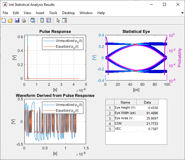
The final equalized impulse response is used to derive the pulse response, statistical eye, and the waveforms.
SerDes System Using Init Subsystem
To understand how an Init subsystem handles statistical analysis in a SerDes system, create a SerDes system using the SerDes Designer app. The SerDes system contains an FFE block on the Tx side and CTLE and DFECDR blocks on the Rx side. Use the default settings for each block.
Access Init Code
Export the SerDes system to a Simulink model. In Simulink, double-click the Tx block to open the Init block. Then double-click the Init block to open the Block Parameters dialog box. Click the Show Init button to open the code pertaining to the Init function of the transmitter.
Reshape Impulse Response and Instantiate Tx System object
The Init function first reshapes the impulse response vector of the analog channel into a 2-D matrix. The first column in the 2-D matrix represents the analog channel impulse response (victim). The subsequent columns (if any are present) represent the crosstalk (aggressors).
%% Impulse response formatting
% Size ImpulseOut by setting it equal to ImpulseIn
ImpulseOut = ImpulseIn;
% Reshape ImpulseIn vector into a 2D matrix using RowSize and Aggressors called LocalImpulse
LocalImpulse = zeros(RowSize,Aggressors+1);
AggressorPosition = 1;
for RowPosition = 1:RowSize:RowSize*(Aggressors+1)
    LocalImpulse(:,AggressorPosition) = ImpulseIn(RowPosition:RowSize-1+RowPosition)';
    AggressorPosition = AggressorPosition+1;
end
Then the Init function initializes the system objects that represent the blocks on the Tx side and sets up the simulation and AMI parameters and the block properties. In this SerDes system, there is only one block on the Tx side, FFE.
%% Instantiate and setup system objects
% Create instance of serdes.FFE for FFE
FFEInit = serdes.FFE('WaveType', 'Impulse');
% Setup simulation parameters
FFEInit.SymbolTime = SymbolTime;
FFEInit.SampleInterval = SampleInterval;
% Setup FFE In and InOut AMI parameters
FFEInit.Mode = FFEParameter.Mode;
FFEInit.TapWeights = FFEParameter.TapWeights;
% Setup FFE block properties
FFEInit.Normalize = true;
Tx Impulse Response Processing
The channel impulse response is then processed by the System object on the Tx side.
%% Impulse response processing via system objects
% Return impulse response for serdes.FFE instance
LocalImpulse = FFEInit(LocalImpulse);
The modified impulse response in 2-D matrix form is reshaped back into an impulse response vector and sent to the Rx side for further equalization.
%% Impulse response reformating
% Reshape LocalImpulse matrix into a vector using RowSize and Aggressors
ImpulseOut(1:RowSize*(Aggressors+1)) = LocalImpulse;
Reshape Impulse Response and Instantiate Rx System object
Similarly, if you look at the Rx Init code, you can see that the Rx Init function first reshapes the output of the Tx Init function into a 2-D matrix.
Then the Init function initializes the System objects that represent the blocks on the Rx side and sets up the simulation and AMI parameters and the block properties. In this case, there are two blocks on the Rx side, CTLE and DFECDR.
%% Instantiate and setup system objects
% Create instance of serdes.CTLE for CTLE
CTLEInit = serdes.CTLE('WaveType', 'Impulse');
% Setup simulation parameters
CTLEInit.SymbolTime = SymbolTime;
CTLEInit.SampleInterval = SampleInterval;
% Setup CTLE In and InOut AMI parameters
CTLEInit.Mode = CTLEParameter.Mode;
CTLEInit.ConfigSelect = CTLEParameter.ConfigSelect;
% Setup CTLE block properties
CTLEInit.Specification = 'DC Gain and Peaking Gain';
CTLEInit.DCGain = [0 -1 -2 -3 -4 -5 -6 -7 -8];
CTLEInit.ACGain = 0;
CTLEInit.PeakingGain = [0 1 2 3 4 5 6 7 8];
CTLEInit.PeakingFrequency = 5000000000;
CTLEInit.GPZ = [0 -23771428571 -10492857142 -13092857142;-1 -17603571428 -7914982142 -13344642857;...
-2 -17935714285 -6845464285 -13596428571;-3 -15321428571 -5574642857 -13848214285;...
-4 -15600000000 -4960100000 -14100000000;-5 -15878571428 -4435821428 -14351785714;...
-6 -16157142857 -3981285714 -14603571428;-7 -16435714285 -3581089285 -14855357142;...
-8 -16714285714 -3227142857 -15107142857];
% Create instance of serdes.DFECDR for DFECDR
DFECDRInit = serdes.DFECDR('WaveType', 'Impulse');
% Setup simulation parameters
DFECDRInit.SymbolTime = SymbolTime;
DFECDRInit.SampleInterval = SampleInterval;
DFECDRInit.Modulation = Modulation;
% Setup DFECDR In and InOut AMI parameters
DFECDRInit.ReferenceOffset = DFECDRParameter.ReferenceOffset;
DFECDRInit.PhaseOffset = DFECDRParameter.PhaseOffset;
DFECDRInit.Mode = DFECDRParameter.Mode;
DFECDRInit.TapWeights = DFECDRParameter.TapWeights;
% Setup DFECDR block properties
DFECDRInit.EqualizationGain = 9.6e-05;
DFECDRInit.EqualizationStep = 1e-06;
DFECDRInit.MinimumTap = -1;
DFECDRInit.MaximumTap = 1;
DFECDRInit.Count = 16;
DFECDRInit.ClockStep = 0.0078;
DFECDRInit.Sensitivity = 0;
Rx Impulse Response Processing
The impulse response that was previously modified by the System objects on the Tx side is then further modified by the System objects on the Rx side.
%% Impulse response processing via system objects
% Return impulse response and any Out or InOut AMI parameters for serdes.CTLE instance
[LocalImpulse, CTLEConfigSelect] = CTLEInit(LocalImpulse);
% Return impulse response and any Out or InOut AMI parameters for serdes.DFECDR instance
[LocalImpulse, DFECDRTapWeights, DFECDRPhase, ~, ~] = DFECDRInit(LocalImpulse);
The final equalized impulse response in 2-D matrix form is reshaped back into an impulse response vector.
Custom User Code Area
Each Init function also contains a section, Custom user code area, where you can customize your own code.
%% BEGIN: Custom user code area (retained when 'Refresh Init' button is pressed)

% END: Custom user code area (retained when 'Refresh Init' button is pressed)
For more information on how you can use the Custom user code area, see Customizing Datapath Building Blocks and Implement Custom CTLE in SerDes Toolbox PassThrough Block.
The code generation of Init function (Refresh Init) can support one or multiple System objects when using the custom PassThrough block. If multiple system objects are present, they must be in series. The first input port must have a waveform as the input. If any waveform output is present, it must be the first output port.
PAMn Thresholds
If you are using a SerDes Toolbox datapath library block, PAMn thresholds in the Init function are maintained
for you automatically. If you are using a custom configuration using a PassThrough, the
code generation of the Init function finds the Data Store Write blocks that
reference the PAMn threshold signals (PAMn_UpperThreshold,
PAMn_CenterThreshold, PAMn_LowerThreshold) and
determines connectivities. The connectivities that are supported are:
Direct connection to System object
Connection to System object through bus selector
Connection to System object through Gain block
Direct connection to Constant block
If the Init code generation cannot find a supported topology, it applies the default PAM4 thresholds.
Advance Init Options
External Init
You can export the Init code to an external MATLAB function, customize it, and then use the customized Init function for rapid
analysis. To export the Init code, select the External Init
option in the block parameters dialog box of either the Tx or Rx Init block, then click
the Refresh Init button. This copies the contents of each of the
Init MATLAB function blocks to txInit.m and rxInit.m
files and links these functions back to the Simulink model. It also creates a runExternalInit.m file that runs
these external Init files in MATLAB.
Once you have customized the Init code and you want to reintegrate the Init function back into the Simulink model, you can disable the External Init option and click the Refresh Init button again. This copies the contents of the Init function into the default Init files and deletes the external Init files.
Disable Default Impulse Response Processing
You can comment out the default impulse processing section of the Init code. This option comments out the code preforming the impulse response processing as shown in the Tx Impulse Response Processing and Rx Impulse Response Processing sections. You can then customize the impulse response processing required for your system design in the Custom User Code Area.
Metrics Used in Statistical Analysis
| Performance Metric | Description |
|---|---|
| Eye Height (V) | Eye height at the center of the BER contour |
| Eye Width (ps) | Eye width of the BER contour |
| Eye Area (V*ps) | Area inside the BER contour eye |
| Eye Linearity | Measure of the variance of amplitude separation among different levels of PAM3, PAM4, PAM8, or PAM16, given by the equation: |
| COM | Channel operating margin, given by the equation: |
| VEC | Vertical eye closure, given by the equation: |