Mux
Combine input signals of same data type and complexity into virtual vector
Libraries:
Simulink /
Commonly Used Blocks
Simulink /
Signal Routing
HDL Coder /
Commonly Used Blocks
HDL Coder /
Signal Routing
Description
The Mux block combines inputs with the same data type and complexity into a virtual vector. You can use multiple Mux blocks to create a mux signal in stages, but the result is flat as if you used a single Mux block.
Ideally, use Mux blocks to group only function-call signals.
While a Mux block can create a virtual vector from signals that have the same data type and complexity, other blocks group signals in ways that provide more flexibility and efficiency.
To group signals or messages, use a Bus Creator block instead of a Mux block. The Bus Creator block creates virtual buses, which give you the flexibility to group elements of different data types and complexity. Virtual buses also let you access elements by name instead of by index. If a block requires a virtual vector instead of a virtual bus, model compilation converts the bus to a vector.
To concatenate input signals, use a Vector Concatenate block instead of a Mux block. The Vector Concatenate block creates a nonvirtual vector, which improves the efficiency of generated code.
For a comparison of mux signals, virtual buses, and concatenated signals, see Explore Composite Interfaces.
Examples
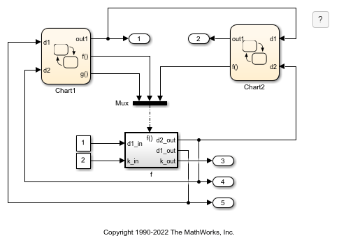
Function-Call Subsystems with Multiple Initiators
A function-call subsystem that is called by multiple different function-call initiators that are grouped by a Mux block.
Ports
Input
Output
Parameters
Block Characteristics
Data Types |
|
Direct Feedthrough |
|
Multidimensional Signals |
|
Variable-Size Signals |
|
Zero-Crossing Detection |
|