View Signal Values Using Port Value Labels
A port value label displays the value for a signal as a label that floats over the signal line in the block diagram, similar to a tooltip or a data tip. You can add and remove port value labels throughout your model before and during simulation. Use port value labels along with other visualization options to understand, analyze, and debug your model.
Port value labels access signal values by probing the data buffers used in the simulation. In some cases, the output port that produces a signal does not correspond directly with a data buffer in the simulation. Adding and removing port value labels in your model does not modify the model in any way, even to make a signal value available for display. When you add a port value label to a signal with a value the software cannot access without modifying the model, the label displays text instead of the signal value to indicate that the signal value is not accessible from that point in the model. For details, see Understand Text Displayed in Port Value Labels.
You can configure settings related to port value labels, including the font size and how frequently the value updates during active simulation. Port value labels and port value label settings are not saved as part of the model.
For more information about options for viewing data, see Decide How to Visualize Simulation Data.
Add and Remove Port Value Labels
When the model is not running in simulation, you can add port value labels to one signal at a time, to a selection of multiple signals, or to all signals in the current block diagram.
Select one or more signals. Then, in the Simulink® Toolstrip, on the Debug tab, in the Tools section, in the Port Values button group, click Show port value label on selected signal
 .
.Select one or more signals. Then, on the Signal tab, click Output Value Labels.
Right-click a selection of one or more signals, and then click Show port value label
 .
.
During simulation, by default, clicking a signal line adds or removes the port value label for that signal line.
If the port value label is visible, clicking the signal line removes the port value label.
If the port value label is not visible, clicking the signal line adds the port value label.
You can control this behavior using the Value Label Display Options dialog box. To disable the single-click option for adding and removing port value labels during simulation:
On the Debug tab, in the Tools section, in the Port Values button group, click the Remove all port value labels button arrow
 .
.Select Options.
In the Value Label Display Options dialog box, in the Display Values section, clear Enable by default during simulation.
After you add port value labels to one or more signal lines, the labels appear on the
signal lines. When you add a port value label before simulation or while paused in
simulation, the label initially shows no data yet because the block
has not executed since you added the port value label.

When you start, continue, or advance the simulation by stepping forward, the port value label updates to display the signal value if the action caused the block that produces the signal value to execute. For example, after clicking Step Forward, the port value label from the previous image updates to display the signal value.
If the port value label displays another message, such as
inaccessible, that port and signal in your model might not
support port value labels. For more information, see Understand Text Displayed in Port Value Labels.
When you remove a port value label, the software does not retain the value that was
displayed. If you immediately add the port value label again, the value shows
no data yet until the block that produces the signal executes
again.
To remove specific port value labels in your model:
Right-click a selection of one or more signals, and then click Show port value label
to cancel the selection.
To remove all port value labels in a model, on the Debug tab, in the Tools section, in the Port Values button group, click Remove all port value labels ![]() .
.
You cannot add or remove port value labels programmatically.
These examples show how to use port value labels to analyze and debug a model:
Configure Port Value Label Settings
You can use the Value Label Display Options dialog box to configure several options related to port value labels, including the font size for the value display, an approximate update rate for the value displayed, and the display format for numeric values.
To open the Value Label Display Options dialog box, on the Debug
tab, in the Tools section, in the Port Values
button group, click the Remove all port value labels button arrow
![]() . Then, select Options.
. Then, select Options.
The settings that you configure apply to all port value labels in the model. Port value label settings are not saved with the model. You cannot configure port value label settings programmatically.
The Approximate refresh interval setting specifies approximately how frequently the software updates the value displayed in each port value label. Often, signal values update during simulation more quickly than you can read them. By default, the Approximate refresh interval for a model is one second. Instead of updating the port value label each time the output method for the source block executes, the software updates the value approximately once per second.
Configure Port Value Labels for Buses
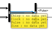
When you add a port value label to a signal line for a bus or a message that carries its payload as a bus, by default, the port value label displays the names and values for all leaf elements of the bus. For example, consider this model that creates a bus hierarchy using output signals from source blocks.

When you add a port value label to the bus main_bus, the port value
label shows no data yet.

After you start, continue, or advance the simulation by stepping forward, the port value label updates to display the names and values for all leaf elements in the bus.

You can select which bus elements to display on the port value label.
Click the port value label for the bus.
In the menu that appears, select the elements to display. Selecting a bus selects all of its elements.
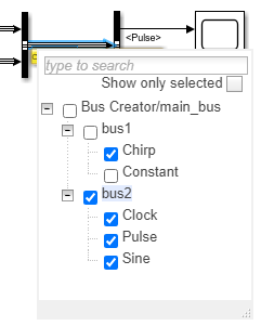
Click anywhere outside the menu to close the menu. The port value label shows only the
selected elements with the text no data yet as the value for each
element. Changing the selection of bus elements to display discards the values
previously displayed in the port value label.
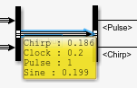
When you simulate the model, the port value label updates to show the values for the selected bus elements.
Consider using these options when working with bus hierarchies that contain many elements:
Search for bus elements by name using the text box at the top of the menu.
To reduce the items displayed in the menu, select Show only selected.
Only the elements selected for display on the port value label show in the menu. To select an additional element, search for the element by name. The search results appear in the menu, where you can select them.
Collapse nodes in the tree that shows the bus hierarchy.
Understand Text Displayed in Port Value Labels
Port value labels might show one of several messages in place of signal values. For example, port value labels on some types of signals, such as function-call signals, display a message that indicates the signal type. In other cases, a port value label might display a message when a signal value is difficult to display in the available space or when the signal value is not accessible at that point in the model.
This table summarizes port value label messages that indicate the signal type.
| Port Value Label Message | Signal Type |
|---|---|
action | Action signals that control execution of action subsystems, such as if-action subsystems |
fcn-call | Function-call signals that control function-call subsystems |
ground | Ground block output signal |
not a data signal | Signal that does not contain valid data, such as the output signal for a block that is commented out |
[m*n] | Two-dimensional signal Instead of the element values, the port value label shows the signal dimensions. |
This table summarizes port value label messages that indicate the software can access the signal value but cannot display the value.
| Port Value Label Message | Context |
|---|---|
| ... | The number of elements in the vector signal exceeds the maximum number of elements to display configured in the Value Label Display Options dialog box. |
click to add signals | The port value label on a bus has no elements selected for display. To select bus elements, click the port value label. |
This table summarizes port value label messages that indicate the software is unable to access the signal value.
| Message | Context |
|---|---|
no data yet | Signal values are not available because the output method of the source block has not executed since the port value label was added. This value also appears for port value labels in model reference instances that do not have normal mode visibility. When you remove a port value label, the software does not retain the value that was displayed. If you immediately add the port value label again, the value shows this message until the block that produces the signal executes again. |
| no message | Insufficient simulation data available. Try starting, continuing, or advancing the simulation. |
inaccessible | The software cannot access the output port value due to the structure of the model. Port value labels show this message for signals that share memory in generated code when the Signal storage reuse (Simulink Coder) model configuration parameter is selected. |
not used | The software cannot access the output port value because the output port value is not used in the simulation. |
removed | The software cannot access the output port value because the source block was removed by block reduction. For more information, see Block reduction. |
optimized | The software cannot access the signal value due to optimization. Port value labels show this message for output signals of blocks that are:
|
unavailable | The software cannot access the output port value because the data is not available. Port value labels show this message when you step back to a simulation time that occurred before you added the port value label. |
When a port value label cannot access the value you want to view, sometimes you can change the model to make the signal value available. For example, in some cases the signal value becomes available when you:
View the signal value using other visualization options, such as the Display block, Scope blocks, and scope viewers.
Mark the signal for logging.
Designate the signal as a test point using the Signal Properties dialog box.
Additional Considerations for Using Port Value Labels
The table summarizes considerations related to using port value labels based on several workflows and modeling patterns.
| Workflow or Modeling Pattern | Considerations for Using Port Value Labels |
|---|---|
| Simulation performance | Selecting Show When Hovering or Toggle When Clicked in the Value Label Display Options dialog box can slow down simulation. |
| Accelerator and rapid accelerator simulations | Port value labels do not show values for output signals of blocks that are optimized out of the simulation target for accelerator mode. Port value labels are not supported for rapid accelerator simulations. |
| Programmatic simulation | Port value labels are not supported for simulations started using
the sim
function. |
| Fixed-point data | Port value labels display the converted double value for signals with fixed-point data types. |
| Model references | Port value labels display data for the model reference instance with normal mode visibility. For more information, see Simulate Multiple Referenced Model Instances in Normal Mode. |
| Subsystem input ports | Blocks that represent input ports inside subsystems are often virtual. Port value labels on input ports inside subsystems show the output value of the block that drives the port when the block that represents the input port is virtual. |
| Variant subsystems | Port value labels cannot access the data for ports of a subsystem that is inside a variant subsystem with no input signals. |
| Disabled subsystems | Whether port value labels display data for output ports of disabled conditionally-executed subsystems depends on the Output when disabled parameter setting for the block that represents the conditionally-executed subsystem. Port value labels do not display data for output ports of enabled subsystems that are disabled. |
| Signal Specification block | Port value labels show the output value for the block that drives the port. |
| Merge block | Port value labels are not supported for signals that connect to input ports of a Merge block. |
| Simscape™ | Port value labels are not supported for physical signals. |
| Model configuration parameters | Port value labels show only values produced when the output method for a block executes. When you specify a refine factor for logging, port value labels do not show values produced to refine the logged data. For more information, see Refine factor. Port value labels might not be able to access data for some signals when you enable these parameters:
|