Create a Simple Mask
Mask a block interactively by using the Mask Editor or mask it programmatically. This example describes how to mask a block using the Mask Editor. To mask a block programmatically, see Control Masks Programmatically.
Step 1: Open Mask Editor
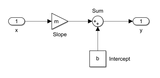
1. Open the model in which you want to mask a block. Consider a model that contains a Subsystem block for the equation of a line:  .
.
2. Select the Subsystem block.
Step 2: Define Mask
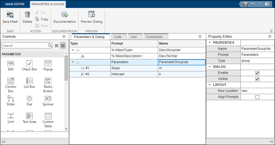
The Mask Editor contains four tabs that enable you to define the block mask and customize the dialog box for the mask. For detailed information on each pane, see Mask Editor Overview. Use Parameters and Dialog tab to add controls like parameters, displays, and action items to the mask dialog box.
1. Add Edit parameter to the block mask, in the left pane, under Parameter, click Edit twice to add two new rows in the Dialog box pane.
2. Type Slope and Intercept in the Prompt column for the two Edit parameters. The value that you enter in Prompt column appears on the mask dialog box. Similarly, type m and b in the Name column. The value you enter in the Name column is the mask parameter name. The mask parameter name must be a valid MATLAB® name.
3. In the right pane, under Property editor, provide values in the Properties, Dialog, and Layout sections.
4. Click Save Mask.
5. To preview the mask dialog box without exiting the Mask Editor, click Preview.
Note: A Simulink® mask parameter cannot reference another parameter on the same mask.
For detailed information, see Parameters & Dialog Pane.
Use the Code pane to specify MATLAB code to control the mask parameters. For example, you can provide a predefined value for a mask parameter. Consider the equation in the example. To set the value of the child block corresponding to m, you can use the set_param function in the code pane.
For detailed information, see Code Pane.
Use Icon tab to create an icon for the block mask. Mask Editor provides you with two modes of authoring block icon.
Graphical Icon Editor: You can create and edit the mask icon of a block through a graphical environment. The various features in Graphical Icon Editor helps you to create icons with ease. Launch Graphical Icon Editor from Mask Editor. For more information, see Graphical Icon Editor Overview.
Mask Drawing Commands: Use a set of mask drawing commands to create masked block icon. You can use the Properties pane on the left to specify icon properties and icon visibility. For detailed information, see Icon drawing commands.
Use Constraints tab to create validations on mask parameters without having to write your own validation code. There are four types of constraints, Parameter Constraint, Cross Parameter Constraints, Port Constraints, and Cross Port Constraints. For detailed information, see Constraints.
Step 3: Operate on Mask
1. You can preview the mask and choose to unmask the block or edit the block mask.
2. Double-click the masked block.
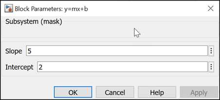
3. Type values in the Slope and Intercept boxes of the mask dialog box. To view the output, simulate the model.
4. Click OK.
5. To edit the mask definition, right-click the subsystem and select Edit Mask.
6. Right-click the subsystem block and select Edit Mask > Look Inside Mask to view the blocks inside the masked subsystem.