Mask Editor Overview
A mask is a custom user interface for a block that hides the block's contents, making it appear to the user as an atomic block with its own icon and parameter dialog box.
The Mask Editor dialog box helps you create and customize the block mask. The Mask Editor dialog box opens when you create or edit a mask. You can access the Mask Editor dialog box by any of these options:
To create mask,
In the Modeling tab, under Component, click Create System Mask.
Select the block and on the Block tab, in the Mask group, click Create Mask. The Mask Editor opens.
To edit mask,
On the Block tab, in the Mask group, click Edit Mask.
Right-click the block and select Edit Mask.
Note
You can also use the keyboard shortcut CTRL + M to open Mask Editor.
The Mask Editor dialog box contains a set of tabbed panes, each of which enables you define a feature of the mask. These tabs are:
Parameters & Dialog Pane: To design mask dialog boxes.
Code Pane: To initialize a masked block using MATLAB® code.
Icon Pane: To create block mask icons.
Constraints: To create constraints.
Note
For information on creating and editing a block mask from command line, see Control Masks Programmatically.
Parameters & Dialog Pane
The Parameters & Dialog pane enables you to design mask dialog boxes using the dialog controls in the Parameters, Display, and Action palettes.
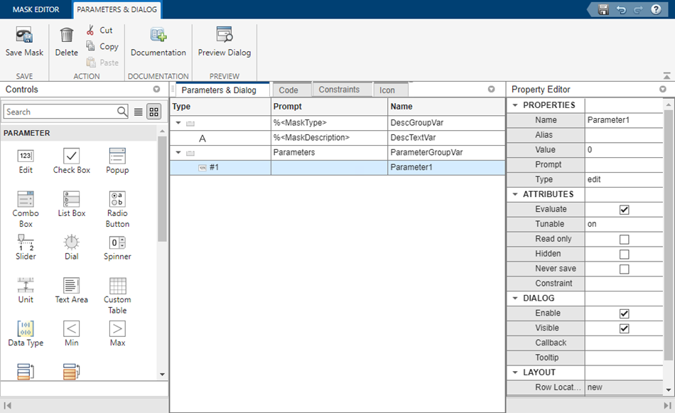
The Parameters & Dialog pane divided into these sections:
Parameter & Dialog Pane
| Section | Section Description | Sub-Section | Sub-Section Description |
|---|---|---|---|
| Controls | Parameters are elements in a mask dialog box that users can interact with to add or manipulate data. | Parameter | Parameters are user inputs that take part in simulation. The Parameters palette has a set of parameter dialog controls that you can add to a mask dialog box. |
| Container | Controls on the Container palette allows you to group controls in the mask dialog box. | ||
| Display | Controls on the Display palette allow you to group dialog controls in the mask dialog box and display text and images. | ||
| Action | Action controls allow you to perform some actions in the mask dialog box. For example, you can click a hyperlink or a button in the mask dialog box. | ||
| Dialog box | You can click or drag and drop dialog controls from the palettes to the Dialog box to create a mask dialog box. | NA | NA |
| Property editor | The Property editor allows you to view and set the properties for the Parameters, Display, Container, and Action controls. | Properties | Defines basic information on all dialog controls, such as Name, Value, Prompt, and Type. |
| Attributes | Defines how a mask dialog control is interpreted. Attributes are related only to parameters. | ||
| Dialog | Defines how dialog controls are displayed in the mask dialog box. | ||
| Layout | Defines how dialog controls are laid out on the mask dialog box. |
Controls
The controls section is sub divided into Parameters, Display, and Action sections. The Controls Table lists the different controls and their description.
Controls Table
| Controls | Description | |
|---|---|---|
Parameters | ||
| Edit | Allows you to enter a parameter value by typing it into the field. You can associate constraints to an
|
| Check box | Accepts a Boolean value. |
| Popup | Allows you to select a parameter value from a list of possible values. You can specify the possible values for the popup parameter using the below options
|
| Combo box | Allows you to select a parameter value from a list of possible values. You can also type a value either from the list or from outside of the list. When you select the Evaluate check box, the associated variable holds the actual value of the selected item. You can associate constraints to a Combo box parameter. |
| Listbox | Allows you to create a list of parameter values. All options of possible values are displayed on the mask dialog box. You can select multiple values from it. |
| Radio button | Allows you to select a parameter value from a list of possible values. All options for a radio button are displayed on the mask dialog box.
|
| Slider | Allows you to slide to values within a range defined by minimum and maximum values. A Slider parameter can accept input as a number or a variable name. If the specified variable is a base workspace or a model workspace variable, you can tune the variable value through the Slider. You can tune the values in the linear scale or logarithmic scale using the Scale drop-down menu You can also control the slider range dynamically. Note Values specified for Slider are auto applied. |
| Dial | Allows you to dial to values within a range defined by minimum and maximum values. A Dial parameter can accept input as a number or a variable name. If the specified variable is a base workspace or a model workspace variable, you can tune the variable value through the Dial. You can tune the values in the linear scale or logarithmic scale using the Scale drop-down menu. You can also control the dial range dynamically. Note Values specified for Dial are auto applied. |
| Spinbox | Allows you to spin through values within a range defined by minimum and maximum values. You can specify a step size for the values. Note Values specified for Spinbox are auto applied.
|
| DataType | Enables you to specify a data type for a mask parameter. You can associate the Min, Max, and Edit parameters with a data type parameter. For more details, see Specify Data Types for an Edit Parameter Using Data Type Parameter. |
| Min | Specifies a minimum value for the edit parameter associated with the DataTypeStr parameter. |
| Max | Specifies a maximum value for the edit parameter associated with the DataTypeStr parameter. |
| Unit | Allows you to set the measurement units for output or input values of a masked block. The Unit parameter can accept any units of measurement as input. For example, rad/sec for angular velocity, meters/sec2 for acceleration, or distance in km or m. |
| Custom Table | Allows you to add tables in the mask dialog box. You can add values as a nested cell array in the Values section of the Property editor. |
| Promote One-to-One | Allows you to selectively promote block parameters from underlying blocks to the mask. Click the Promote One-to-One to open the Promoted Parameter Selector dialog box. In this dialog box, you can select the block parameters that you want to promote. Click OK to close it. |
| Promote Many-to-One | Allows you to promote all underlying block parameters to the mask. When you promote all parameters, the promote operation deletes parameters that have been promoted previously. |
Container | ||
| Group box | Container to group other dialog controls and containers in the mask dialog box. |
| Tab | Tab to group dialog controls in the mask dialog box. A tab is contained within a tab container. A tab container can have multiple tabs. |
Table | Container to group the Edit, Check box, and the Popup parameters in a tabular form. You can also search and sort the content listed within the Table container. For more information, see Use Mask Containers to Group Parameters on Mask Dialog Box. | |
| Collapsible Panel | Container to group dialog controls similar to Panel. You can choose to expand or collapse the CollapsiblePanel dialog controls. |
| Panel | Container to group of dialog controls. You use a Panel for logical grouping of dialog controls. See Design Mask Dialog Box Layout |
Mask Part Reference | Container to create and save mask parameters and dialog controls in an XML file. You can refer to the XML file in multiple masked blocks to reuse the mask parameters and dialog controls. For more information, see Reuse Mask Parameters and Dialog Controls Across Multiple Masked Blocks | |
Display | ||
| Text | Text displayed in the mask dialog box. |
| Image | Image displayed in the mask dialog box. The file path of the image must be an absolute path. |
| Text Area | Add a custom text or MATLAB code in the mask dialog box. |
| Listbox Control | Display the text as list on the mask dialog box. You can select multiple values (Ctrl + click). |
Tree Control | Allows you to display value in a hierarchical tree of possible values. You can select multiple values (Ctrl + click). See Examples for more information. | |
|
| Lookup Table Control | Allows you to visualize n-dimensional table and breakpoint data. |
|
| Web Browser | Allows you to open a website on previewing the dialog box. Enter the address in the URL property. |
Action | ||
| Hyperlink | Hyperlink text displayed on the mask dialog box. |
| Button | Button controls on the mask dialog box. You can program button for specific actions. You can also add an image on a button controls. |
For more information on the mask parameters, explore the example model Types of Mask Parameters.
Dialog box
You can build a hierarchy of dialog controls by dragging them from a Controls section to the Parameters and Dialog tab. You can also click the palettes on the Controls section to add the required control to the Parameters and Dialog tab. You can add a maximum of 32 levels of hierarchy in the Parameters and Dialog tab.
The Parameters and Dialog section contains:
Type:— Type of the dialog control and it cannot be edited. It also displays a sequence number for parameter dialog controls.
Prompt:— Prompt text for the dialog control.
Name:— Name is auto-populated and uniquely identifies the dialog controls. You can choose to add a different value (valid MATLAB name) in the Name field and must not match the built-in parameter name.
Search:— Search parameters, dialog controls, and containers based on name or prompt.
Filter:— Refine the search result based on mask parameter properties and their values. The properties include Type, Evaluate, Tunable, and Visible.
The Parameter controls are displayed in light blue background whereas the Display and Action controls are displayed in white background on the Dialog box.
You can move a dialog control in the hierarchy, you can copy and paste a dialog control, you can also delete a node. For more information, see Dialog Control Operations.
Property editor
The Property editor allows you to view and set the properties for Parameter, Display, Container, and Action dialog controls. The Property editor for Parameter is shown:
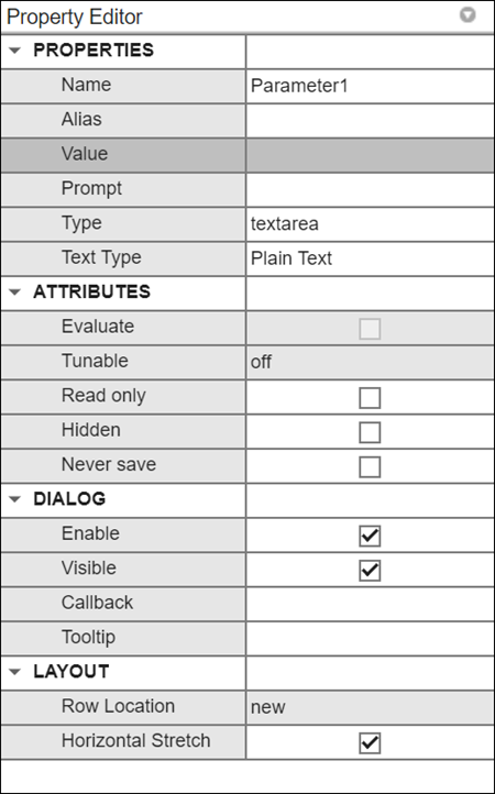
You can set the following properties for Parameter, Action, and Display dialog controls. For more information, see the Property editor table.
Property editor
| Property | Description | ||||||||||||
|---|---|---|---|---|---|---|---|---|---|---|---|---|---|
| Properties | |||||||||||||
Name | Uniquely identifies the dialog control in the mask dialog box. The Name property must be set for all dialog controls. | ||||||||||||
Alias | Alternate name for the dialog control. For example, you can also use the alternate name of the parameter to set the value of the parameter. | ||||||||||||
Value | Value of the Parameter. The Value property applies only to the Parameter dialog controls. | ||||||||||||
Prompt | Label text that identifies the parameters in a mask dialog box. The Prompt property applies to all dialog controls except Panel and Image dialog control. | ||||||||||||
Type | Type of the dialog control. You can use the Type field to change the Parameter and Container types. You cannot change any container type to Tab and vice versa. | ||||||||||||
Expand | Allows you to specify if the collapsible panel dialog control is expanded or collapsed, by default. | ||||||||||||
Type options | The Type options property allows you to set specific Parameter properties. The Type options property applies to the Popup, Radio button, DataTypeStr, and Promoted parameters. | ||||||||||||
File path | You can add an image to a mask using the Image dialog control. You can also display an image on a Button dialog control. In either case, provide the path to the image in the File path property that is enabled for these two dialog controls. For the Button dialog control, specify an empty character vector for the Prompt property in order for the image to be displayed. Note that, when you provide the
filepath, do not use the quote marks (' '). For example, if
you want to add an image, provide the filepath as:
| ||||||||||||
Word wrap | The Word wrap property enables word wrapping for long text. The Word wrap property applies only for Text dialog control. | ||||||||||||
Maximum and Minimum | The Maximum and Minimum properties enable you to specify a range for controls like Spinbox, Slider, and Dial. | ||||||||||||
Step size | Allows you to specify a step size for the values. This property applies only for Spinbox dialog control. | ||||||||||||
Tooltip | Allows you to specify a tooltip for the selected dialog control type. The tooltip is visible when you hover the cursor over a dialog control on the mask dialog box. You can add tooltips for all dialog controls type except for Group box, Tab, CollapsiblePanel, and Panel. | ||||||||||||
Scale | Allows you to set the tuning scale as
linear or log for
Slider and Dial
dialog controls. | ||||||||||||
Table Parameter | Specify table data for the Lookup Table parameter. | ||||||||||||
| Table Unit | Specify units for the table data. | ||||||||||||
| Table Display Name | Specify display name for the Lookup Table control. | ||||||||||||
| Breakpoint Parameters | Specify breakpoint parameters for the Lookup
Table control. For example,
{'torque','engine speed'}
| ||||||||||||
| Breakpoint Units | Specify the units for breakpoint parameters. For example,
{'Nm','rpm'} | ||||||||||||
| Data Specification | You can specify data for table and breakpoint parameters by explicitly specifying the values in the parameters or through a data object | ||||||||||||
| Lookup Table Object | Specify the name of the data object for the table and breakpoint parameters values | ||||||||||||
| Text Type | Specify the type of text for the Text Area parameter. It can accept Plain Text, HTML Text, and MATLAB code. The Text Area parameter has the capability to process the HTML code and display the output in the mask dialog box. Similarly, it can process the MATLAB code and display the output. | ||||||||||||
| Attributes | |||||||||||||
Evaluate | If you enter a MATLAB expression as a mask parameter input, Simulink® handles the entry in one of two ways:
The Evaluate option is selected by default for the Edit, Check Box and Popup mask parameters. | ||||||||||||
Tunable | Set the Tunable property of the mask parameter to change the value of a mask parameter during simulation. If the masked parameter does not support parameter tuning, Simulink ignores the Tunable property of the mask parameter. Such parameters are disabled on the mask dialog box when simulating. The tunable options of a mask parameter are:
Depending on the value specified for the Tunable attribute and the simulation mode, the mask parameter can either be read-only or read/write.
For information about parameter tuning and the blocks that support it, see Tune and Experiment with Block Parameter Values. Note During code generation, the parameter is displayed in
the generated code as a variable only when the
Default parameter behavior is
set as | ||||||||||||
Read only | Indicates that the parameter cannot be modified. The read-only attribute can be used if you want to create a persistent parameter which can hold on to certain value or data but cannot be directly modified. | ||||||||||||
Hidden | Indicates that the parameter must not be displayed in the mask dialog box. | ||||||||||||
Never save | Indicates that the parameter value never gets saved in the model file. | ||||||||||||
Constraint | Allows you to add constraints to the selected parameter. | ||||||||||||
| Dialog box | |||||||||||||
Enable | By default Enable is selected. If you clear this option, the selected control becomes unavailable for edit. Masked block users cannot set the value of the parameter. | ||||||||||||
Visible | The selected control appears in the mask dialog box only if this option is selected. | ||||||||||||
Callback | MATLAB code that you want Simulink to execute when a user applies a change to the selected control. Simulink uses a temporary workspace to execute the callback code. | ||||||||||||
|
Note The Enable/Visible properties allows to create dynamic block dialog boxes where parameters are enabled or displayed based on a change in other parameter’s value. | |||||||||||||
| Layout | |||||||||||||
Item location | Allows you to set the location for the dialog control to appear in the current row or a new row. | ||||||||||||
Align Prompts | Allows you to align the parameters on the mask dialog box. This option is supported for all the Display control types except Table. | ||||||||||||
Prompt location | Allows you to set the prompt location for the dialog control on either the top or to the left of the dialog control. You cannot set the Prompt location property for Check box, Dial, DataTypeStr, Collapsible Panel and Radiobutton. | ||||||||||||
Orientation | Allows you to specify horizontal or vertical orientation for sliders and radio buttons. | ||||||||||||
Horizontal Stretch | By default, all controls stretch horizontally when you
resize the mask dialog box. This option helps manage the
stretch properties of controls in the same row inside a
container. For example, consider a popup parameter and a
button in the same row within a container. Upon resizing,
you may want the popup parameter to stretch but not the
button. To achieve this, set the Horizontal
Stretch property of the popup parameter to
| ||||||||||||
Documentation Pane
The Documentation pane enables you to define or modify the type, description, and help text for a masked block.
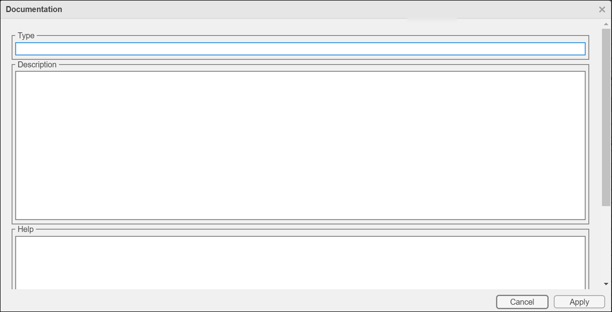
Type
The mask type is a block classification that appears in the mask
dialog box and on all Mask Editor panes for the block. When
Simulink displays a mask dialog box, it suffixes (mask)
to the mask type. To define the mask type, enter it in the
Type field. The text can contain any valid MATLAB character, but cannot contain line breaks.
Description
The mask description is summary help text that describes the block's purpose or function. By default, the mask description is displayed below the mask type in the mask dialog box. To define the mask description, enter it in the Description field. The text can contain any legal MATLAB character. Simulink automatically wraps long lines. You can force line breaks by using the Enter key.
Help
The Online Help for a masked block provides information in addition to that provided by the Type and Description fields. This information appears in a separate window when the masked block user clicks the Help button on the mask dialog box. To define the mask help, type one of these in the Help field:
URL specification
weborevalcommandLiteral or HTML text
Provide a URL
If the first line of the Help field is a URL, Simulink passes the URL to your default web browser. The URL can begin with
https:, www:,
file:, ftp:, or
mailto:. Examples:
https://www.mathworks.com
file:///c:/mydir/helpdoc.html
Once the browser is active, MATLAB and Simulink have no further control over its actions.
Provide a web Command
If the first line of the Help field is a
web command, Simulink passes the command to MATLAB, which displays the specified file in the HTML Viewer.
Example:
web([docroot '/MyBlockDoc/' get_param(gcb,'MaskType') '.html'])
See the MATLAB
web command documentation for
details. A web command used for mask help cannot return
values.
Provide an eval Command
If the first line of the Help field is an
eval command, Simulink passes the command to MATLAB, which performs the specified evaluation. Example:
eval('open My_Spec.doc')See MATLAB
eval command documentation for
details. An eval command used for mask help cannot return
values.
Provide Literal or HTML Text
If the first line of the Help field is not a URL, or a
web or an eval command, Simulink displays the text in the system web browser under a heading that
is the value of the Mask type field. The text can contain
any legal MATLAB character, line breaks, and any standard HTML tag, including tags
like img that display images.
Simulink first copies the text to a temporary folder, then displays the
text using the web command. If you want the text
to display an image, you can provide a URL path to the image file, or you can
place the image file in the temporary folder. Use tempdir to find the temporary
folder that Simulink uses for your system.
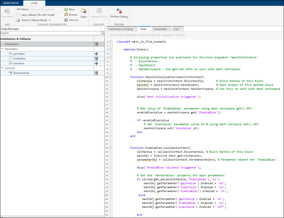
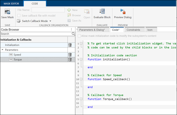
Code Pane
The Code pane gives you an integrated view of block initialization and parameter callback code. The Mask Editor code functionalities are like those in the MATLAB Editor, with some limitations. For example, the autocomplete functionality is supported, but you cannot set a breakpoint in your code. You can organize mask initialization and mask callback code in a separate MATLAB class file. See Organize Mask Initialization and Callbacks in a MATLAB File for more information.
When you open a model, Simulink locates the visible masked blocks that reside at the top level of the model or in an open subsystem. Simulink only executes the initialization commands for these visible masked blocks if they meet either of the following conditions:
The masked block has icon drawing commands.
Note
Simulink does not initialize masked blocks that do not have icon drawing commands, even if they have initialization commands.
The masked block belongs to a library and has the Allow mask initialization code to modify the subsystem's content setting enabled.
Initialization commands for all masked blocks in a model run when you:
Update the diagram
Start simulation
Start code generation
Click Apply on the dialog box
Editing and saving the callback.
Initialization commands for an individual masked block run when you:
Change any of the mask parameters that define the mask, such as
MaskDisplayandMaskInitialization, by using the Mask Editor or theset_paramcommand.Rotate or flip the masked block, if the icon depends on the initialization commands.
Cause the icon to be drawn or redrawn, and the icon drawing depends on initialization code.
Change the value of a mask parameter by using the block dialog box or the
set_paramcommand.Copy the masked block within the same model or between different models.
The Code pane contains the controls described in this section.
Initialization and Parameter Callbacks
Click ![]() to add the initialization code template and
parameter callback template in the editor. You can enter any valid MATLAB expression, consisting of MATLAB functions and scripts, operators, and variables defined in the
mask workspace. Initialization commands run in the mask workspace, not the base
workspace.
to add the initialization code template and
parameter callback template in the editor. You can enter any valid MATLAB expression, consisting of MATLAB functions and scripts, operators, and variables defined in the
mask workspace. Initialization commands run in the mask workspace, not the base
workspace.
The Code pane provides you an integrated view of the mask initialization code and the mask callback code. To add parameter callback code, click the plus button next to the parameter from the Parameter list, the skeleton for the callback code appears. Enter MATLAB commands for the callback.
Rules for Initialization Commands
Following rules apply for mask initialization commands:
Do not use initialization code for dynamic mask dialog boxes as initialization is not generally performed when the mask dialog box changes. Instead, use the mask callbacks for the relevant parameters, which are executed immediately when the given parameter is updated.
Avoid prefacing variable names in initialization commands with
MaskParam_L_andMaskParam_M_. These specific prefixes are reserved for use with internal variable names.Avoid using
set_paramcommands to set parameters of blocks residing in masked subsystems that reside in the masked subsystem being initialized. See Modify Structure of Subsystem Blocks Using Self- Modifiable Mask for details.
Allow mask initialization code to modify subsystem's Content
This check box is enabled only if the masked block resides in a library. Selecting this option allows you to modify the parameters of the masked block. If the masked block is a masked subsystem, this option allows you to add or delete blocks and set the parameters of the blocks within that subsystem. If this option is not selected, an error is generated when a masked library block tries to modify its contents in any way.
Icon Pane
The Icon pane helps you to create a block icon that contains descriptive text, state equations, image, and graphics. You can author block icon using either Graphical Editor or Mask Drawing Commands.
Graphical Icon Editor
Graphical Editor: You can create and edit the mask icon of a block through a graphical environment. The various features in Graphical Icon Editor helps you to create icons with ease. Launch Graphical Icon Editor from Mask Editor.
![]()
Interactive graphical environment: Use graphical tools like pen, curvature, text, scissor, connector, and equation (which supports LaTeX) to create rich graphical icons. Grids, smart guides, and rulers help you to create pixel-perfect icons. Apart from the drawing tools, a few built-in shapes, such as Resistor, Inductor, and Rotational Damper, are readily available.
Element browser: Element browser lists all the elements in the icon.
Hide or unhide an element in the icon.
Lock or unlock an element so that you do not accidentally change the shape or position of an element while working on other elements of the icon.
Name each element in the icon for easy identification.
Port binding/unbinding: The number of ports on each block is pre-defined if you are creating or modifying the block using block context. For example, the number of ports for Simscape™ blocks or Aerospace blocks are pre-defined and they appear on the block icon. You can also define the number of ports on the block icon if you are creating or modifying a block without a block context.
Conditional visibility: Hide or unhide an element of the block based on the block parameters or mask parameters.
Preview options: Preview the icon in Simulink using preview options such as horizontal stretch, flip, or scale. You can also preview the icons with modified block parameters.
Display elements that fit the size of the icon: The first-fit feature helps you to display only the elements that fit in the size of the icon when you resize the block.
Position elements relatively: The auto layout constraint feature helps you to position each element relative to other elements on the canvas.
Text Parameterization: You can view the evaluated value of a block parameter or mask parameter on the block icon. Enter the block parameter name or a placeholder in Parameter/Value that will return the text or value during runtime. To see the evaluated value of a block parameter on the block icon, preview the icon on Simulink canvas.
To know more about Graphical Icon Editor, see Graphical Icon Editor Overview.
Mask Icon Drawing Commands
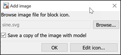
Mask editor provides you the skeleton for each of the drawing commands. You can set an image for the mask icon. Click Add Image to import an image.
The Mask Icon Drawing Commands pane is divided into these sections:
Properties: Provides a list of different controls that can be applied on the mask icon.
Preview: Displays the preview of the block mask icon.
Icon drawing commands: Enables you to draw mask icon by using MATLAB code.
Note
You can create static and dynamic block mask icon. For more information, see Mask Display and Initialization Commands.
Properties. Properties available in the right pane are a list of controls that allow you to specify attributes on the mask icon. These options are,
Block Frame. The block frame is the rectangle that encloses the block. You can choose
to show or hide the frame by setting the Block Frame
parameter to Visible or
Invisible. The default is to make the block
frame visible. For example, this figure shows visible and invisible block
frames for an AND gate block.
Note
If you set the icon transparency to
Transparent, Simulink does not hide the block frame even if you set the Block Frame property toInvisible.
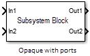
Icon Transparency. The icon transparency can be set to Opaque,
Opaque with ports, or
Transparent, based on whether you want to
hide or show what is underneath the icon. The default option
Opaque hides information such as port
labels.
For a subsystem block, if you set the icon transparency to
Opaque with ports the port labels are
visible.
Note
For the
Opaqueoption to hide the port labels, there must be an icon drawing command added in the mask editor.
Icon Units. This option controls the coordinate system used by the drawing commands.
It applies only to the plot, text, and
patch drawing commands. You can select from among
these choices: Autoscale,
Normalized, and
Pixel.
Autoscalescales the icon to fit the block frame. When the block is resized, the icon is also resized. For example, this figure shows the icon drawn using these vectors:X = [0 2 3 4 9]; Y = [4 6 3 5 8];
![Icon showing the shape drawn by using the coordinates X = [0 2 3 4 9]; Y = [4 6 3 5 8];](blkdrawauto.gif)
The lower-left corner of the block frame is (0,3) and the upper-right corner is (9,8). The range of the x-axis is 9 (from 0 to 9), while the range of the y-axis is 5 (from 3 to 8). When there are multiple drawing commands with varying x and y axes, the overall plot limit is considered while rendering these commands.
Normalizeddraws the icon within a block frame whose bottom-left corner is (0,0) and whose top-right corner is (1,1). Only X and Y values from 0 through 1 appear. When the block is resized, the icon is also resized. For example, this figure shows the icon drawn using these vectors:X = [.0 .2 .3 .4 .9]; Y = [.4 .6 .3 .5 .8];
![Icon showing the shape drawn using the coordinates X = [.0 .2 .3 .4 .9]; Y = [.4 .6 .3 .5 .8];](blkdrawnorm2.gif)
Pixeldraws the icon with X and Y values expressed in pixels. The icon is not automatically resized when the block is resized. To force the icon to resize with the block, define the drawing commands in terms of the block size. For example, the X and Y values are specified relative to the position of the block.position = get_param(gcb,'Position'); blockWidth= position(3) - position(1) ; blockHeight= position(4) - position(2); xVertices = [0, blockWidth, blockWidth, 0]; yVertices = [0, 0, blockHeight, blockHeight]; patch(xVertices, yVertices, [1, 0, 0]);

Icon Rotation. When the block is rotated or flipped, you can choose whether to rotate or
flip the icon or to have it remain fixed in its original orientation. The
default is not to rotate the icon. The icon rotation is consistent with
block port rotation. This figure shows the results of choosing
Fixed and Rotates
icon rotation when the AND gate block is rotated.
Port Rotation. This option enables you to specify a port rotation type for the masked block. The choices are:
defaultPorts are reordered after a clockwise rotation to maintain a left-to-right port numbering order for ports along the top and bottom of the block and a top-to-bottom port numbering order for ports along the left and right sides of the block.
physicalPorts rotate with the block without being reordered after a clockwise rotation.
The default rotation option is appropriate for control systems and other modeling applications where block diagrams typically have a top-down and left-right orientation. It simplifies editing of diagrams, by minimizing the need to reconnect blocks after rotations to preserve the standard orientation.
Similarly, the physical rotation option is appropriate for electronic, mechanical, hydraulic, and other modeling applications where blocks represent physical components and lines represent physical connections. The physical rotation option more closely models the behavior of the devices represented (that is, the ports rotate with the block as they would on a physical device). In addition, the option avoids introducing line crossings as the result of rotations, making diagrams easier to read.
For example, the following figure shows two diagrams representing the same transistor circuit. In one, the masked blocks representing transistors use default rotation and in the other, physical rotation.
Both diagrams avoid line crossings that make diagrams harder to read. The next figure shows the diagrams after a single clockwise rotation.
Note
The rotation introduces a line crossing the diagram that uses default rotation but not in the diagram that uses physical rotation. Also that there is no way to edit the diagram with default rotation to remove the line crossing. See Flip or Rotate Blocks for more information.
Run Initialization. The Run initialization option enables you to control the execution of the mask initialization commands. The choices are:
Off (Default): Does not execute the mask initialization commands. When the mask drawing commands do not have dependency on the mask workspace, it is recommended to specify the value of Run initialization as Off. Setting the value to Off helps in optimizing Simulink performance as the mask initialization commands are not executed.
On: Executes the mask initialization commands if the mask workspace is not up-to-date. When this option is specified, the mask initialization commands are executed before executing the mask drawing commands irrespective of the mask workspace dependency of the mask drawing commands.
Analyze: Executes the mask initialization commands only if there is mask workspace dependency. When this option is specified, Simulink executes the mask initialization commands before executing the mask icon drawing commands. The Analyze option is for backward compatibility and is not recommended otherwise. It is recommended that the Simulink models from R2016b or before are upgraded using the Upgrade Advisor.
For more information, see Draw Mask Icon Using Drawing Commands.
Preview. This section displays the preview of block mask icon. Block mask preview is available only if the mask contains an icon drawing.
When you add an icon drawing command and click Apply, the preview image refreshes and is displayed in the Preview section of Icon pane.
Icon drawing commands. Add code to the editor to draw a block icon. You can use the list of commands in the left pane to draw a block icon.
Mask icon drawing commands
| Drawing Command | Description | Syntax Example | Preview |
|---|---|---|---|
color | Change drawing color of subsequent mask icon drawing commands | color('red');
port_label('output',1,'Text') | |
disp | Display text on the masked icon. | disp('Gain') | |
dpoly | Display transfer function on masked icon | dpoly([0 0 1], [1 2 1], 'z') | |
droots | Display transfer function on masked icon | droots([-1], [-2 -3], 4) | |
fprintf | Display variable text centered on masked icon | fprintf('Sum = %d', 7) | |
image | Display RGB image on masked icon To add
an image, select a masked block and on the
Block tab, click Add
Image. You can also add multiple images to the mask icon through multiple image commands. Note The image should be on MATLAB path. | image('sine.svg') | |
patch | Draw color patch of specified shape on masked icon | patch([0 10 20 30 30 0], [10 30 20 25 10 10],[1
0 0]) | |
plot | Draw graph connecting series of points on masked icon | plot([10 20 30 40], [10 20 10
15]) | |
port_label | Draw port label on masked icon | port_label('output', 1, 'xy') | |
text | Display text at specific location on masked icon. You must select
|
| |
block_icon | Promote icon of a block contained in a Subsystem to the Subsystem mask |
Here, the icon of block is promoted to its Subsystem block. For more information, see Draw Mask Icon Using Drawing Commands. |
Note
Simulink does not support mask drawing commands within anonymous functions.
The drawing commands execute in the same sequence as they are added in the
text box. Drawing commands have access to all variables in the mask
workspace. If any drawing command cannot successfully execute, the block
icon displays question marks ![]() .
.
The drawing commands execute after the block is drawn in these cases:
Changes are made and applied in the mask dialog box.
Changes are made in the Mask Editor.
Changes are done to the block diagram that affects the block appearance, such as rotating the block.
Constraints
Mask parameter constraints help you to create validations on a mask parameter without having to write your own validation code. There are three types of constraints, Parameter Constraint, Cross Parameter Constraints, and Port Constraints.

Parameter Constraint: A mask can contain parameters that accept user input values. You can provide input values for mask parameters using the mask dialog box. Constraints ensure that the input for the mask parameter is within a specified range. For example, consider a masked Gain block. You can set a constraint where the input value must be between 1 and 10. If you provide an input that is outside the specified range, an error displays. Constraint Browser on the left pane helps you to manage Shared Constraints.
Cross Parameter Constraint: Cross-parameter constraints are applied among two or more Edit or Combobox type mask parameters. You can use a cross parameter constraint when you want to specify scenarios such as, Parameter1 must be greater than Parameter2.
Port Constraint: You can specify constraints on the input and output ports of a masked block. The port attributes are checked against the constraints when you compile the model.
Cross Port Constraint: Create cross port constraints to validate compile-time signal attributes among ports of the same masked block. For example, you can set a constraint among the input and output port signals of the masked block to have the same data type.
Additional Options
Following buttons appear on the Mask Editor:
Save Mask applies the mask settings and leaves the Mask Editor open.
The Preview Dialog applies the changes you made, and opens the mask dialog box.
The Delete Mask deletes the mask and closes the Mask Editor. To create the mask again, select the block and on the Block tab, in the Mask group, click Create Mask.
Copy Mask copies the mask definitions from Simulink library blocks. Search for the desired block and click Copy Mask to import the mask definition from an existing block.
Evaluate Block evaluates the callback and initialization code.
Shared Constraint Manager launches standalone constraint manager. Manage multiple shared constraint files independently of a block context using Shared Constraint Manager. For more information, see Author Parameter and Port Constraints Using Standalone Constraint Manager.