Use Analog I/O Drivers
Control systems have unique requirements for I/O devices used with Simulink® Desktop Real-Time™ applications. For information about writing custom I/O device drivers to work with Simulink Desktop Real-Time applications, see Integrate C Code in Custom S-Functions.
Configure I/O Driver Characteristics
Simulink Desktop Real-Time applications use I/O boards provided by many hardware vendors. These boards are often used for data acquisition independently of Simulink Desktop Real-Time software. In such environments, board manufacturers usually provide their own I/O device drivers for data acquisition purposes. This use differs significantly from the behavior of drivers provided with Simulink Desktop Real-Time software.
In data acquisition applications, data is often collected in a burst or frame consisting of many points, possibly 1,000 or more. The burst of data becomes available once the final point is available. This approach is not suitable for automatic control applications, because it results in unacceptable latency for most of the data points.
In contrast, drivers used by Simulink Desktop Real-Time applications capture a single data point at each sample interval. The software gives considerable effort to minimize the latency between collecting a data point and using the data in the control system algorithm. Sometimes a board can specify a maximum sample rate (for data acquisition) higher than the rates achievable by Simulink Desktop Real-Time applications. For data acquisition, such boards usually acquire data in bursts and not in the point-by-point fashion required by control systems.
Normalize Scaling for Analog Inputs
Simulink Desktop Real-Time software allows you to normalize I/O signals internal to the block diagram. Generally, inputs represent real-world values such as angular velocity, position, temperature, and pressure. This ability to normalize signals allows you to:
Apply your own scale factors
Work with meaningful units without having to convert from voltages
When using an Analog Input block, you select the range of the external
voltages that the board receives, and you select the block output signal. For example,
you could set the voltage range to 0 to +5 V, and the block
output signal as Normalized unipolar, Normalized
bipolar, Volts, or
Raw.
If you prefer to work with units of voltage within your Simulink block diagram, you can select Volts.
To apply your own scaling factor, select Normalized
unipolar or Normalized bipolar, add a
Gain block, and add an offset to convert the value to a meaningful
value in your model.
If you prefer nonrounded integer values from the analog-to-digital conversion
process, you can select Raw.
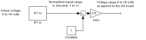
0 to +5 Volts and Normalized bipolar
From the Input range list, select 0 to +5 V, and from
the Block output signal list, select
Normalized bipolar. This example converts a normalized
bipolar value to volts, but you could also easily convert directly to another
parameter in your model.
0 to 5 volts --> ([-1 to 1] normalized + 1) * 2.5
In your block diagram, you can convert the normalized value to volts as follows.
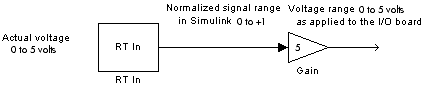
0 to +5 V and Normalized unipolar
From the Input range list, select 0 to +5
V, and from the Block output signal list,
select Normalized unipolar. This example converts a
normalized unipolar value to volts, but you could also easily convert directly to
another parameter in your model.
0 to 5 volts --> ([0 to 1] normalized * 5.0
In your block diagram, you can convert the normalized value to volts as follows.
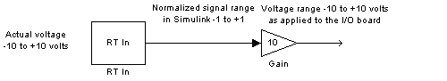
-10 to +10 V and Normalized bipolar
From the Input range list, select -10 to
+10 V, and from the Block output signal
list, select Normalized bipolar. This example converts a
normalized bipolar value to volts, but you could also easily convert directly to
another parameter in your model.
-10 to 10 volts --> [-1 to +1] normalized * 10
In your block diagram, you can convert the normalized value to volts as follows.
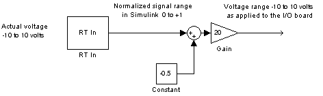
-10 to +10 V and Normalized unipolar
From the Input range list, select -10 to
+10 V, and from the Block output signal
list, select Normalized unipolar. This example converts a
normalized bipolar value to volts, but you could also easily convert directly to
another parameter in your model.
-10 to 10 volts --> ([0 to 1] normalized - 0.5) * 20
In your block diagram, you can convert the normalized value to volts as follows.
Normalize Scaling for Analog Outputs
Analog outputs are treated in an equivalent manner to analog inputs.
For example, assume that the voltage range on the D/A converter is set to
0 to +5 volts and the Block input
signal is selected as Normalized bipolar.
With this configuration, a Simulink signal of amplitude -1 results in an output voltage
of 0 volts. Similarly, a Simulink signal of amplitude +1 results in an output voltage
of +5 volts.
For another example, assume that the voltage range on the D/A converter is set to
-10 to +10 volts and the Block input
signal is selected as Normalized bipolar.
With this configuration, a Simulink signal of amplitude -1 results in an output voltage
of -10 volts. Similarly, a Simulink signal of amplitude +1 results in an output voltage
of +10 volts.
As required by your selected voltage range, adjust your signal amplitudes using a Gain block, Constant block, and Summer block.