Flexible T Beam
T-beam with elastic properties for deformation

Libraries:
Simscape /
Multibody /
Body Elements /
Flexible Bodies /
Beams
Description
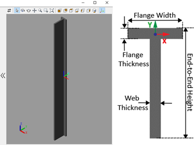
The Flexible T Beam block models a slender beam with a T-shaped cross-section, also known as a T-beam. The T-beam consists of one horizontal component, known as a flange, and one vertical component, which is called a web. The T-beam can have small and linear deformations. These deformations include extension, bending, and torsion. The block calculates the beam cross-sectional properties, such as the axial, flexural, and torsional rigidities, based on the geometry and material properties that you specify.
The geometry of the T-beam is an extrusion of its cross-section. The beam cross-section, defined in the xy-plane, is extruded along the z-axis. To define the cross-section, you can specify its dimensions in the Geometry section of the block dialog box. The figure shows a T-beam and its cross-section. The reference frame of the beam is located at the midpoint of the intersection line of the mid-planes of the web and flange.
For more information on modeling flexible beams, see Overview of Flexible Beams.
Ports
Frame
Parameters
Geometry
Distance from the top face of the flange to the bottom end of the web. The
End-to-End Height is also known as the beam depth.
Note
The End-to-End Height must be larger than the Flange Thickness.
Distance between the two faces of the web.
Note
The Web Thickness must be smaller than the Flange Width.
Distance between the two ends of the flange.
Distance between the two faces of the flange.
Extrusion length of the beam. The beam is modeled by extruding the specified cross-section along the z-axis of the local reference frame. The extrusion is symmetric about the xy-plane, with half of the beam being extruded in the negative direction of the z-axis and half in the positive direction.
Stiffness and Inertia
Method to use to specify the stiffness and inertia properties, specified as Calculate from Geometry or Custom.
When you set the parameter to Calculate from Geometry, the block
calculates the stiffness and inertia properties based on the specified density,
Young’s modulus, and Poisson’s ratio or shear modulus. Set the parameter to
Custom to manually specify the stiffness and
inertia properties.
Mass per unit volume of material—assumed here to be distributed uniformly throughout the beam. The default value corresponds to aluminum.
Dependencies
To enable this parameter, under the Stiffness and Inertia
section, set Type parameter to Calculate from
Geometry.
Elastic properties in terms of which to parameterize the beam. These properties are commonly available from materials databases.
Dependencies
To enable this parameter, under the Stiffness and Inertia
section, set Type parameter to Calculate from
Geometry.
Young's modulus of elasticity of the beam. The greater its value, the stronger the resistance to bending and axial deformation. The default value corresponds to aluminum.
Dependencies
To enable this parameter, under the Stiffness and Inertia
section, set Type parameter to Calculate from
Geometry.
Poisson's ratio of the beam. The value specified must be greater than or equal to
0 and smaller than 0.5. The default value
corresponds to aluminum.
Dependencies
To enable this parameter, under the Stiffness and Inertia
section, set Type parameter to Calculate from
Geometry and set the Specify parameter to
Young's Modulus and Poisson's Ratio.
Shear modulus (or modulus of rigidity) of the beam. The greater its value, the stronger the resistance to torsional deformation. The default value corresponds to aluminum.
Dependencies
To enable this parameter, under the Stiffness and Inertia
section, set Type parameter to Calculate from
Geometry and set the Specify parameter to
Young's and Shear Modulus.
Calculated values of the mass and stiffness sectional properties of the beam. Click Update to calculate and display those values.
The properties given include Centroid and Shear Center. The centroid is the point at which an axial force extends (or contracts) the beam without bending. The shear center is that through which a transverse force must pass to bend the beam without twisting.
The stiffness sectional properties are computed as follows:
Axial Rigidity: EA
Flexural Rigidity: [EIx, EIy]
Cross Flexural Rigidity: EIxy
Torsional Rigidity: GJ
The mass sectional properties are computed as follows:
Mass per Unit Length: ρA
Mass Moment of Inertia Density: [ρIx, ρIy]
Mass Product of Inertia Density: ρIxy
Polar Mass Moment of Inertia Density: ρIp
The equation parameters include:
A — Cross-sectional area
ρ — Density
E — Young's modulus
G — Shear modulus
J — Torsional constant (obtained from the solution of Saint-Venant's warping partial differential equation)
The remaining parameters are the relevant moments of area of the beam. These are calculated about the axes of a centroidal frame—one aligned with the local reference frame but located with its origin at the centroid. The moments of area are:
Ix, Iy — Centroidal second moments of area:
,
Ixy — Centroidal product moment of area:
,
Ip — Centroidal polar moment of area:
,
where xc and yc are the coordinates of the centroid.
Centroid of the beam cross section, specified as a 2-by-1 array. The array specifies the x and y coordinates of the centroid with respect to the beam reference frame.
Dependencies
To enable this parameter, in the Stiffness and Inertia section, set Type to Custom.
Intersection of the neutral axis and cross section, specified as a 2-by-1 array. The array specifies the x and y coordinates of the centroid with respect to the beam reference frame.
Dependencies
To enable this parameter, in the Stiffness and Inertia section, set Type to Custom.
Beam shear center, specified as a 2-by-1 array. The array specifies the x and y coordinates of the point with respect to the beam reference frame.
Dependencies
To enable this parameter, in the Stiffness and Inertia section, set Type to Custom.
Resistance against the deformation along the beam longitudinal direction, specified as a scalar. This parameter specifies the element of the stiffness matrix.
Dependencies
To enable this parameter, in the Stiffness and Inertia section, set Type to Custom.
Resistance against bending deformations, specified as a 2-by-1 array. The array specifies the and elements of the stiffness matrix.
Dependencies
To enable this parameter, in the Stiffness and Inertia section, set Type to Custom.
Resistance against the bending deformation about the x-axis in response to bending moment about the y-axis, specified as a scalar. This parameter specifies the element of the stiffness matrix.
Dependencies
To enable this parameter, in the Stiffness and Inertia section, set Type to Custom.
Resistance against twisting about the longitudinal axis of the beam, specified as a scalar. This parameter specifies the element of the stiffness matrix.
Dependencies
To enable this parameter, in the Stiffness and Inertia section, set Type to Custom.
Center of mass, specified as a 2-by-1 array. The array specifies the x and y coordinates of the point with respect to the beam reference frame.
Dependencies
To enable this parameter, in the Stiffness and
Inertia section, set Type to
Custom.
Mass per unit length, specified as a scalar. This parameter specifies the element of the mass matrix.
Dependencies
To enable this parameter, in the Stiffness and Inertia section, set Type to Custom.
Resistance against rotation about the x and y axes, specified as a 2-by-1 array. The array specifies the and elements of the mass matrix.
Dependencies
To enable this parameter, in the Stiffness and
Inertia section, set Type to
Custom.
Resistance against rotation about the x-axis due to the moment about the y-axis, specified as a scalar. This parameter specifies the element of the mass matrix.
Dependencies
To enable this parameter, in the Stiffness and
Inertia section, set Type to
Custom.
Damping
Damping method to apply to the beam:
Select
Noneto model undamped beams.Select
Proportionalto apply the proportional (or Rayleigh) damping method. This method defines the damping matrix [C] as a linear combination of the mass matrix [M] and stiffness matrix [K]:,
where α and β are the scalar coefficients.
Select
Uniform Modalto apply the uniform modal damping method. This method applies a single damping ratio to all the vibration modes of the beam. The larger the value, the faster vibrations decay.The chosen reference conditions impact the types of modes to which the damping ratio applies. For details on reference conditions, see Reference Conditions. When you use modal reduction for the flexible body, only a subset of modes is retained. For details on modal reduction, see Reduce the Degrees of Freedom for a Flexible Body.
Coefficient, α, of the mass matrix. This parameter defines damping proportional to the mass matrix [M].
Dependencies
To enable this parameter, set Type to
Proportional.
Coefficient, β, of the stiffness matrix. This parameter defines damping proportional to the stiffness matrix [K].
Dependencies
To enable this parameter, set Type to
Proportional.
Damping ratio, ζ, applied to all beam vibration modes in the uniform modal damping model. The larger the value, the faster beam vibrations decay.
When ζ = 0, the beam is undamped. If the boundary conditions applied to the beam exactly match the chosen reference conditions, ζ < 1 yields underdamped modal decay, ζ = 1 corresponds to critical damping, and ζ > 1 yields overdamped dissipation. When the boundary conditions and reference conditions do not match, the effect of the chosen damping ratio varies. For details of reference condition, see Reference Conditions.
Dependencies
To enable this parameter, set Type to Uniform
Modal.
Discretization
Number of finite elements in the beam model. Increasing the number of elements always improves accuracy of the simulation. But practically, at some point, the increase in accuracy is negligible when there are many elements. Additionally, a higher number of elements increases the computational cost and slows down the speed of the simulation.
Reference Conditions
Specify the type of reference conditions to apply. For details, see Reference Conditions.
Linearized Mean Axes: The body frame of reference follows the instantaneous center of mass and the flexible body exhibits unconstrained vibration modes of deformation.Body-Fixed: Choose a body-attached frame as the body frame of reference. The deformation of the flexible body exhibits free vibration mode shapes with zero translational and rotational deformation at the location of the body frame of reference.
Enter the name of the connection frame to use as the body frame of reference. The frame name is case-sensitive. Ensure the selected frame is exposed as a port on the block. You cannot use the R frame, which is the reference frame of the fictitious undeformed body.
Dependencies
To enable this parameter, set Type to
Body-Fixed.
Select to expose the R port, which represents the reference frame of the fictitious undeformed body. Note that the R frame is not physically attached to the flexible body.
The R port must not be rigidly connected to any blocks that exert forces and torques or possess inertia.
Fidelity
Method to use to model flexible bodies, specified as
None or Modally
Reduced. Set the parameter to None
to use full nodal elastic coordinates generated by the finite-element method or
set the parameter to Modally Reduced to use the modal
transformation method to reduce the elastic coordinates of the body. For both
settings, the block uses the floating frame of the reference formulation [1-2]
to couple the body with its elastic deformation.
Retained modes, specified as an integer in range [0, n], where n is the number of elastic degrees of freedom of the body. If you set the number to 0 the flexible body is treated as a rigid body.
Dependencies
To enable this parameter, set Reduction to Modally
Reduced.
Graphic
Type of the visual representation of the beam, specified as From Geometry or None. Set the parameter to From Geometry to show the visual representation of the beam. Set the parameter to None to hide the beam in the model visualization.
Parameterizations for specifying visual properties. Select Simple to specify Color and Opacity. Select Advanced to specify more visual properties, such as Specular Color, Ambient Color, Emissive Color, and Shininess.
Dependencies
To enable this parameter, set Type to From Geometry.
Color of the graphic under direct white light, specified as an [R G B] or [R G B A] vector on a 0–1 scale. An optional fourth element (A) specifies the color opacity on a scale of 0–1. Omitting the opacity element is equivalent to specifying a value of 1.
Dependencies
To enable this parameter, set:
Type to
From GeometryVisual Properties to
Simple
Graphic opacity, specified as a scalar in the range of 0 to 1. A scalar of 0 corresponds to completely transparent, and a scalar of 1 corresponds to completely opaque.
Dependencies
To enable this parameter, set:
Type to
From GeometryVisual Properties to
Simple
Color of the light due to diffuse reflection, specified as an [R,G,B] or [R,G,B,A] vector with values in the range of 0 to 1. The vector can be a row or column vector. The optional fourth element specifies the color opacity. Omitting the opacity element is equivalent to specifying a value of 1.
The diffuse color reflects the main color of the rendered beam and provides shading that gives the rendered object a three-dimensional appearance.
Dependencies
To enable this parameter, set:
Type to
From GeometryVisual Properties to
Advanced
Color of the light due to specular reflection, specified as an [R,G,B] or [R,G,B,A] vector with values in the range of 0 to 1. The vector can be a row or column vector. The optional fourth element specifies the color opacity. Omitting the opacity element is equivalent to specifying a value of 1. This parameter changes the color of the specular highlight, which is the bright spot on the rendered beam due to the reflection of the light from the light source.
Dependencies
To enable this parameter, set:
Type to
From GeometryVisual Properties to
Advanced
Color of the ambient light, specified as an [R,G,B] or [R,G,B,A] vector with values in the range of 0 to 1. The vector can be a row or column vector. The optional fourth element specifies the color opacity. Omitting the opacity element is equivalent to specifying a value of 1.
Ambient light refers to a general level of illumination that does not come directly from a light source. The ambient light is light that has been reflected and re-reflected so many times that it is no longer coming from any particular direction. You can adjust this parameter to change the shadow color of the rendered beam.
Dependencies
To enable this parameter, set:
Type to
From GeometryVisual Properties to
Advanced
Color due to self illumination, specified as an [R,G,B] or [R,G,B,A] vector in the range of 0 to 1. The vector can be a row or column vector. The optional fourth element specifies the color opacity. Omitting the opacity element is equivalent to specifying a value of 1.
The emission color is color that does not come from any external source, and therefore seems to be emitted by the beam itself. When a beam has an emissive color, the beam can be seen even if there is no external light source.
Dependencies
To enable this parameter, set:
Type to
From GeometryVisual Properties to
Advanced
Sharpness of the specular light reflections, specified as a scalar number on a 0–128 scale. Increase the shininess value for smaller but sharper highlights. Decrease the value for larger but smoother highlights.
Dependencies
To enable this parameter, set:
Type to
From GeometryVisual Properties to
Advanced
Frames
Select to expose the A port.
Select to expose the B port.
Click the Create button ![]() to open a pane for creating a new
body-attached frame. In this pane, you can specify the name, origin, and
orientation for the frame.
to open a pane for creating a new
body-attached frame. In this pane, you can specify the name, origin, and
orientation for the frame.
To name the custom frame, click the text field of the Frame Name parameter. The name identifies the corresponding port on the beam block and in the tree view pane of the Multibody Explorer.
To select the Frame Origin for the custom frame, use one of the following methods:
At Reference Frame Origin: Make the new frame origin coincident with the origin of the reference frame of the undeformed beam.
Based on Geometric Feature: Make the new frame origin coincident with the center of the selected undeformed geometry feature. Valid features include surfaces, lines, and points. Select a feature from the visualization pane, then click Use Selected Feature to confirm the location of the origin. The name of the origin location appears in the field below this option.
To define the orientation of the custom frame, under the Frame Axes section, select the Primary Axis and Secondary Axis of the custom frame and then specify their directions.
Use the following methods to select a vector for specifying the directions of the primary and secondary axes. The primary axis is parallel to the selected vector and constrains the remaining two axes to its normal plane. The secondary axis is parallel to the projection of the selected vector onto the normal plane.
Along Reference Frame Axis: Selects an axis of the reference frame of the undeformed beam.
Based on Geometric Feature: Selects the vector associated with the chosen geometry feature of the undeformed beam. Valid features include surfaces and lines. The corresponding vector is indicated by a white arrow in the visualization pane. You can select a feature from the visualization pane and then click Use Selected Feature to confirm the selection. The name of the selected feature appears in the field below this option.
Frames that you have created. N is a unique identifying
number for each custom frame.
Click the text field to edit the name of an existing custom frame.
Click the Edit button
 to edit other aspects of the
custom frame, such as origin and axes.
to edit other aspects of the
custom frame, such as origin and axes.Click the Delete button
 to delete the custom
frame.
to delete the custom
frame.
Dependencies
To enable this parameter, create a frame by clicking New Frame.
References
[1] Shabana, Ahmed A. Dynamics of Multibody Systems. Fourth edition. New York: Cambridge University Press, 2014.
[2] Agrawal, Om P., and Ahmed A. Shabana. “Dynamic Analysis of Multibody Systems Using Component Modes.” Computers & Structures 21, no. 6 (January 1985): 1303–12. https://doi.org/10.1016/0045-7949(85)90184-1.
Extended Capabilities
Version History
Introduced in R2020a