Simplify Stateflow Charts by Incorporating Active State Output
This example shows how active state data can simplify the design of some Stateflow® charts because you do not have to maintain data that is highly correlated to the chart hierarchy. When you enable active state data, Stateflow reports state activity through an output port to Simulink® or as local data in your chart. This example shows how to simplify the design of a Stateflow chart by adding active state output data. For more information, see Monitor State Activity Through Active State Data.
In the legacy model old_sf_car, the Stateflow chart shift_logic tracks child state activity in gear_state by updating the value of the output data gear.
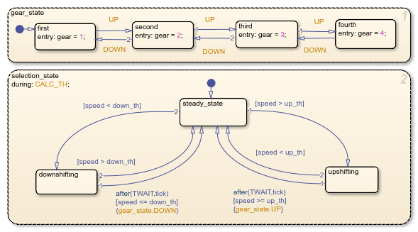
By incorporating active state data, the model sf_car avoids manual data updates reflecting chart activity. Instead, the chart outputs child state activity automatically through the active state output gear.

Modify the Model
To simplify the design of the old_sf_car model, eliminate data that is highly correlated to the chart hierarchy and enable automatic monitoring of child state activity in gear_state.
Step 1: Eliminate Manual Tracking of State Activity
In the model
old_sf_car, open the chartshift_logic.To open the Symbols pane, in the Modeling tab, select Symbols Pane.
In each substate of
gear_state, delete the entry action assigning a value to the output data variablegear.In the Symbols pane, right-click the output variable
gearand selectDelete.
Step 2: Enable Active State Output
Open the Property Inspector. In the Modeling tab, select Property Inspector.
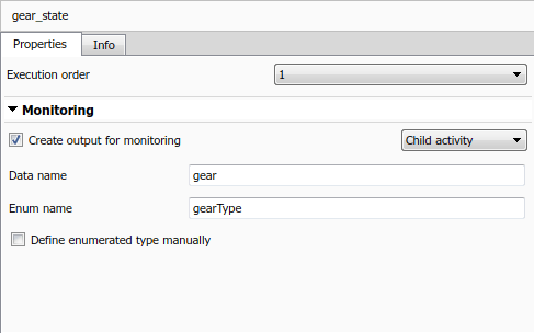
In the Stateflow Editor, select the state
gear_state.In the Property Inspector, select the Create output for monitoring check box and choose
Child activity.In the Data name field, enter the name
gearof the active state data.In the Enum name field, enter the name
gearTypeof the enumeration data type for the active state data.
Step 3: Connect Signal to Simulink Blocks
In the Simulink model, add a Cast To Double block. This block converts the enumerated output from the Stateflow chart to a signal of type
double. For more information, see Data Type Conversion (Simulink).Connect the output signal
gearfrom theshift_logicchart to the Cast To Double block.Connect the output signal from the Cast To Double block to the Transmission subsystem.
Add a Memory (Simulink) block. This block prevents an algebraic loop between the Stateflow chart and the Threshold Calculation subsystem.
Make a second connection from the output signal from the Cast To Double block to the Memory block.
Connect the output of the Memory block to the Threshold Calculation subsystem.

View Simulation Results
The output signal gear is an enumerated type managed by Stateflow. You can view the active state output signal gear during simulation by connecting the chart to a Scope block. The names of the enumerated values match the names of the substates in gear_state. The additional enumerated value of None indicates time steps when no child is active.

See Also
Data Type Conversion (Simulink) | Memory (Simulink)