Create Interfaces
You can create interfaces between components in System Composer™ to structure transmitted data. Use composite data interfaces with data elements or value types to manage data defined on ports. Assign a data interface or value type to a data element so the data element inherits attributes and reuses data. Use the model below as a starting point before adding interfaces using the Interface Editor.
For interfaces terminology, see Define Port Interfaces Between Components.
To manage interfaces shared between models in data dictionaries, see Manage Interfaces with Data Dictionaries. For information on physical interfaces, see Specify Physical Interfaces on Ports.
Open Model
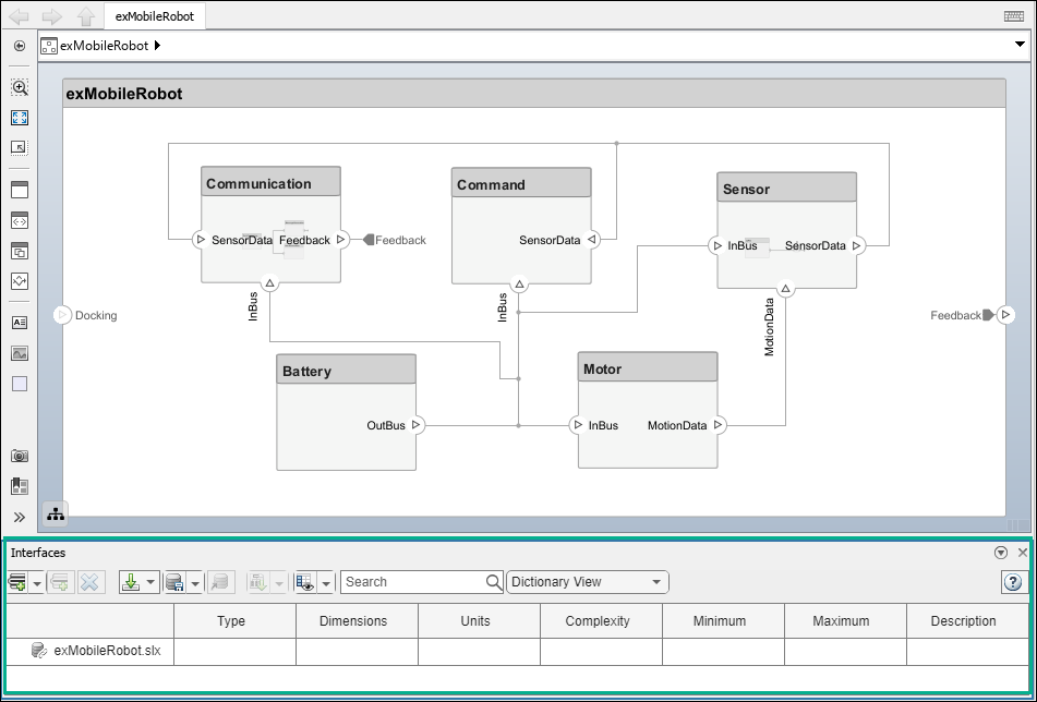
Open the mobile robot platform architecture model.
Open Interface Editor
To open the Interface Editor, navigate to Modeling > Interface Editor. The Interface Editor will open at the bottom of the canvas.
Create Composite Data Interfaces
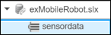
To add a new data interface definition, click the ![]() icon. Name the data interface
icon. Name the data interface sensordata.
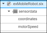
To add a data element to the data interface, click the ![]() icon. Data interface and data element names must be valid MATLAB® variable names.
icon. Data interface and data element names must be valid MATLAB® variable names.
You can delete data interfaces and data elements in the Interface Editor using the ![]() button.
button.
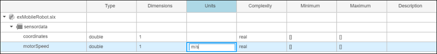
You can view and edit the properties of an element in the Property Inspector. Right-click the data element and select Inspect Properties. For data interfaces, use the Property Inspector to apply stereotypes.
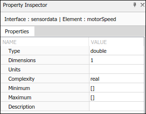
For a comparative view, you can edit data element properties from the relevant Interface Editor columns.
Create Value Types as Interfaces
Since R2021b
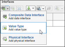
To add a value type in the Interface
Editor, select the down arrow next to the ![]() icon and select Value Type. Name
the value type
icon and select Value Type. Name
the value type motorSpeedType. Value type names must be valid
MATLAB variable names.
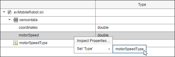
Right-click the motorSpeed data element and select Set 'Type' > motorSpeedType. The data element motorSpeed is assigned to the value
type motorSpeedType.
Any data changes on the motorSpeedType value type is propagated to
the motorSpeed data element. You can reuse value types any number of
times. Data changes on a value type will propagate to each data element that uses the
value type.
Nest Interfaces to Reuse Data
A nested interface contains another data interface. Create a nested data interface by assigning a data interface as the type of a data element. For information about the corresponding buses, see Define Multilevel Bus Hierarchy Using Type Editor.
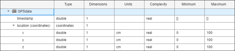
For example, let coordinates be a data interface that consists of x, y, and z coordinates. The GPSdata data interface includes location and a timestamp. If the location data element is in the same format as the coordinates interface, you can set its type to coordinates. Right-click location and select Set 'Type' > coordinates. The available interface options include all value types and all data interfaces in the model, except the parent of the data element.
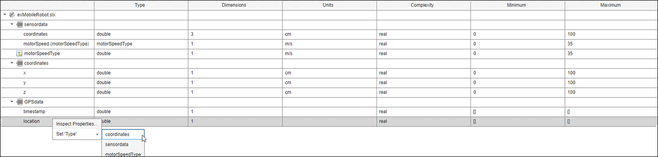
The nested data interface displays the inherited data elements.
Note
To change the number of columns that display in the Interface Editor, right-click the columns. Select or clear the desired columns to show or hide them.
See Also
Functions
addInterface|getSubElement|getPortElement|removeInterface|addElement|removeElement|connect|setInterface|addValueType