Simulation 3D UAV Vehicle
Place UAV vehicle in 3D visualization

Libraries:
UAV Toolbox /
Simulation 3D
Description
Note
Simulating models with the Simulation 3D UAV Vehicle block requires Simulink® 3D Animation™.
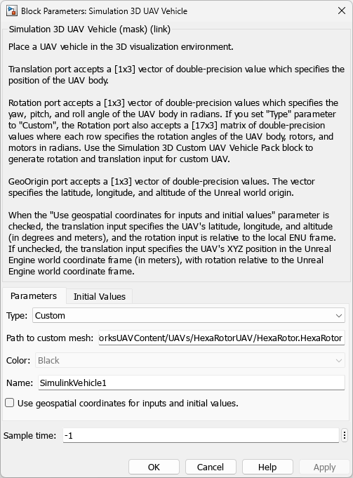
The Simulation 3D UAV Vehicle block implements an unmanned aerial vehicle (UAV) in a 3D simulation environment. This environment is rendered using the Unreal Engine® from Epic Games®. The block uses the input (X, Y, Z) position and input (roll, pitch, yaw) attitude of the UAV in the simulation.
To use this block, ensure that the Simulation 3D Scene Configuration block
is in your model. If you set the Sample time parameter of the
Simulation 3D UAV Vehicle block to -1, the block inherits
the sample time specified in the Simulation 3D Scene Configuration block.
Tip
The Simulation 3D UAV Vehicle block must execute before the Simulation 3D Scene Configuration block. That way, the Simulation 3D UAV Vehicle block prepares the signal data before the Unreal Engine 3D visualization environment receives it. To check the block execution order, right-click the blocks and select Properties. On the General tab, confirm these Priority settings:
Simulation 3D Scene Configuration —
0Simulation 3D Vehicle —
-1
For more information about execution order, see Block Execution Order.
Examples
Open the tiltRotorUAVModel.slx Simulink® model.
open_system("tiltRotorUAVModel")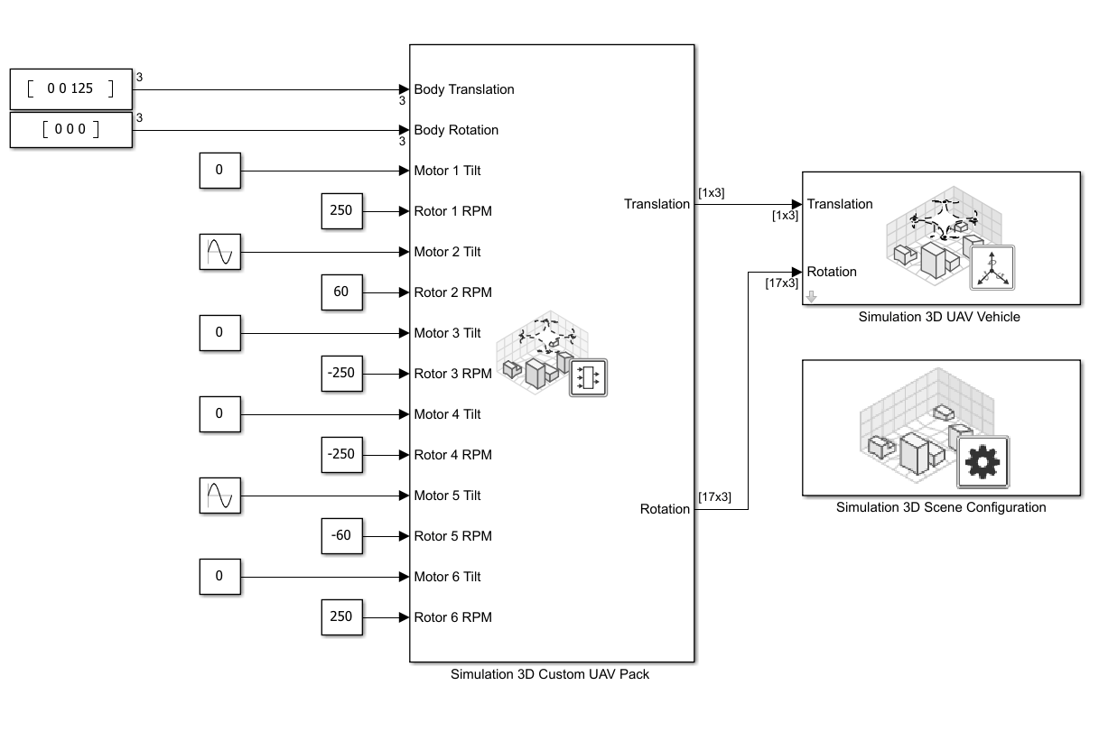
This model uses the Simulation 3D UAV Vehicle block to simulate a custom Hexarotor UAV in 3D environment. The Type parameter is specified to Custom, and the Path to custom mesh is specified to /MathWorksUAVContent/UAVs/HexaRotorUAV/HexaRotor.HexaRotor.
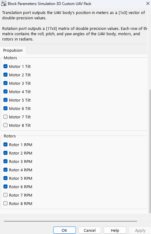
This model uses the Simulation 3D Custom UAV Pack block to generate the translation and rotation inputs. The block is configured to accept the body translation, body rotation, tilt angles for motors 1 to 6, and angular velocities of rotors 1 to 6.
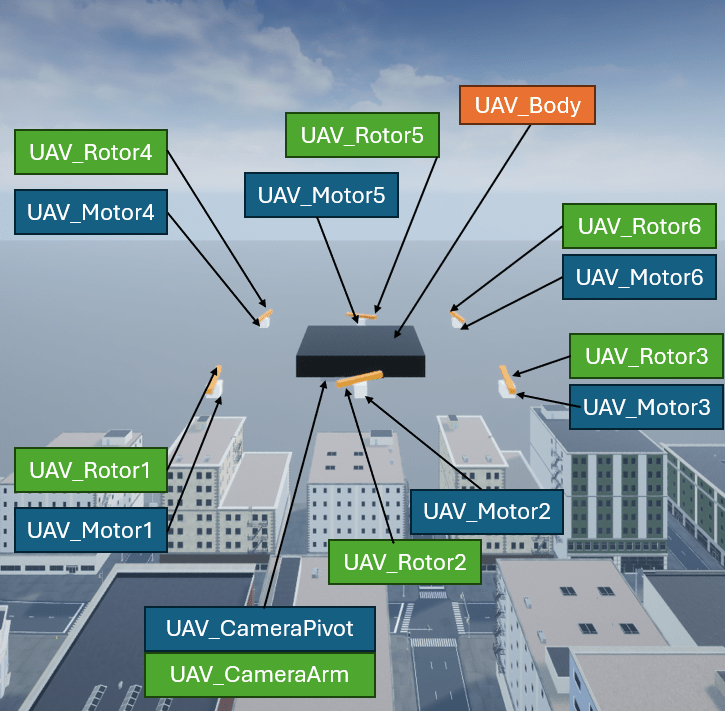
The Hexarotor custom mesh is configured with the bone hierarchy that is shown in the following image. For more details on how to configure custom UAV mesh for simulation in Unreal Engine, visit Prepare Custom UAV Vehicle Mesh for Unreal Engine Scenario Simulation.
In this example, the Hexarotor UAV is configured with the following input:
UAV_Body rotation angle — 0 radian of roll, pitch, and yaw angles.
UAV_Motor1 tilt angle — 0 radian.
UAV_Rotor1 angular velocity — 250 RPM, clockwise.
UAV_Motor2 tilt angle — pi/2 radian, oscillating at a rate of 1 rad/s.
UAV_Rotor2 angular velocity — 60 RPM, clockwise.
UAV_Motor3 tilt angle — 0 radian.
UAV_Rotor3 angular velocity — 250 RPM, counter-clockwise.
UAV_Motor4 tilt angle — 0 radian.
UAV_Rotor4 angular velocity — 250 RPM, counter-clockwise.
UAV_Motor5 tilt angle — pi/2 radian, oscillating at a rate of 1 rad/s.
UAV_Rotor5 angular velocity — 60 RPM, counter-clockwise.
UAV_Motor6 tilt angle — 0 radian.
UAV_Rotor6 angular velocity — 250 RPM, clockwise.
Run the tiltRotorUAVModel.slx Simulink model to start the simulation.

You can also run this example with an Octarotor UAV mesh by specifying the Path to custom mesh parameter of the Simulation 3D UAV Vehicle block as /MathWorksUAVContent/UAVs/OctaRotorUAV/OctaRotor.OctaRotor and running the model again.

Extended Examples
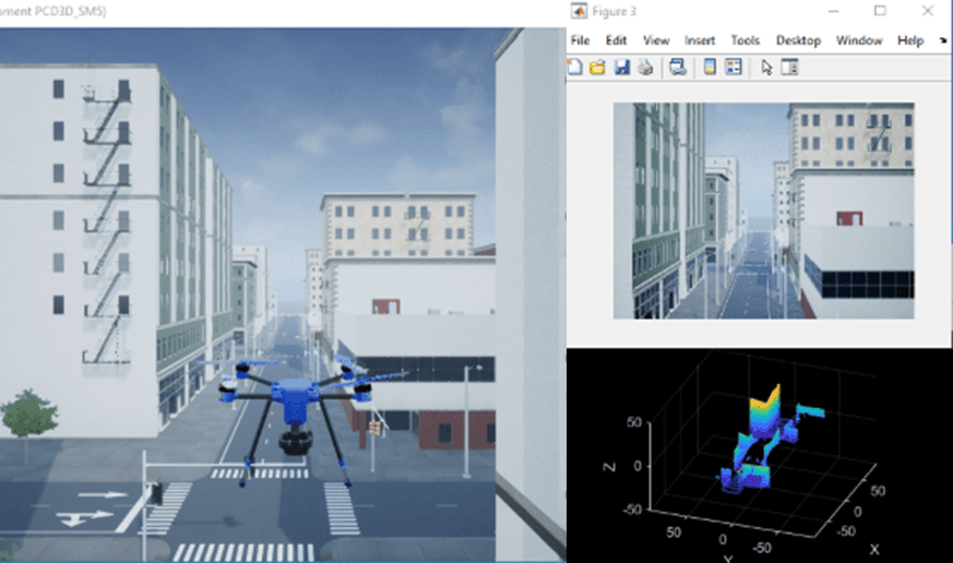
UAV Package Delivery
Simulate a small multicopter simulation taking off, flying, and landing in a city environment.
Visualize VTOL UAV Takeoff and Forward Transition
Visualize VTOL UAV during vertical takeoff and transition in Unreal Engine.