GIWAXS evaluation - scripting
Version 1.0.0 (1.93 MB) by
Karol Vegso
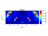
This m-script is a simple evaluator of GIWAXS data using scripting.
This program uses GIXSGUI / GIXSDATA Matlab library. You must install GIXSGUI / GIXSDATA in your Matlab, and cite this project from Advanced Photon Source, USA. The m-script <GIWAXS_evaluation_scripting.m> si very simple. It has only single input <path_to_script>. You define here the path to the script text file. There are two input files <GIWXAS_script_file.txt> with scripting values and <calibration_file.txt> with calibration information.
The calibration text file contains only single line <Pilatus 487 195 0.172 0.172 8.04 75.424 2 1 4 0.5 2.0 244.281 182.449 244.281 151.785>. The first information is type of detector, e.g. Pilatus. It can be also 'Other' or ‘MAR165’ or something else. The number 487 is the number of pixels in horizontal direction. The number 195 means number of pixels in vertical direction, as here I used Pilatus 100K detector. The values of 0.172 0.172 are the pixel size in horizontal direction and pixel size in vertical direction, respectively. The value of 8.04 keV is the energy of X-ray photons, here it is for CuKalpha radiation. The value of 75.424 is the sample-detector distance or SDD. The value of 2 means that you are measuring in reflection mode or GIWAXS mode. If you are measuring in transmission, there should be value of 1. The value of 1 is for phi mode (% PhiMode, 1 for [-180°, 180°], 2 for [0°, 360°], 3 for [-270°, 90°], 4 for [-90°, 270°]). The value if 1 means that phi orientation is in the range of [-180°, 180°]. The value of 4 means that unpolarized beam was used (% PolarizationMode, 1, 2, 3, 4 for none, horiozntal, vertical, unpolarized), because I did measuremnt with laboratory X-ray source. If you performed experiment with synchrotron beam, you can set polarization of your X-ray beam. The value of the 0.5 is connected to the horizontal poarization fraction (horizontal polarization fraction, 1 for fully horizontally polarized beam,). If unpolarized beam is considered, this value makes not sense. The value of 2.0 is the angle of incidence. The values of 244.281 182.449 244.281 151.785 means position of the primary beam or Beam0 in the horizontal direction in pixels, the position of the primary beam or Beam0 in the vertical direction in pixels, the position of the reflected / specular beam in the horizontal direction in pixels, and the position of the reflected / specular beam in the vertical direction in pixels.
The actual script <GIWAXS_evaluation_scripting.m> contains many lines. The single line is for example <d:\GIWAXS_measurements\2023\NathanRodkey\270123\sample_1_ai_2p0deg sample_1_ai_2p0deg .tif sample_1 400 150 -1.97 1.97 0 1.56 0 5000 lin 400 150 -29 29 0 20.4 0 5000 lin 180 0.9 1.1 -90 90 lin 250 -90 90 0.0 2.42 lin lin d:\GIWAXS_measurements\2023\NathanRodkey\270123\script\270123_calibration_NathanRodkey.txt 0>.
The path <d:\GIWAXS_measurements\2023\NathanRodkey\270123\sample_1_ai_2p0deg> si the path to the folder with detector image, which is here analyzed.
The <sample_1_ai_2p0deg> si the name of the single image.
The <.tif> is the extension of the image. Here, it is tif image file.
The <sample_1> is the arbitrary name of the image.
The <400 150 -1.97 1.97 0 1.56 0 5000 lin> means that detector image will be reshaped to 400 sampling points in q_r (horizontal direction), and 150 sampling points in q_z (vertical direction). The detector image will be reshaped in q_r from -1.97 reciprocal angstroms to 1.97 reciprocal Angstroms. The detector image will be reshaped from 0 reciprocal Angstroms to 1.56 reciprocal Angstroms in q_z direction. The intensity value in plots will be scaled from 0 counts to 5000 counts in linear scale mode.
The <400 150 -29 29 0 20.4 0 5000 lin> means that detector image will be reshaped to 400 sampling points in 2theta_final (horizontal direction), and 150 sampling points in alpha_final (vertical direction). The detector image will be reshaped in 2theta from -29 degrees to +29 degrees. The detector image will be reshaped from 0 degrees to 20.4 degrees in alpha_final direction. The intensity value in plots will be scaled from 0 counts to 5000 counts in linear scale mode.
The <180 0.9 1.1 -90 90 lin> means that chi-cut will be cut on the 180 points integrated from q value of 0.9 reciprocal Angstroms to the q value of 1.1 reciprocal Angstroms. The chi-cut will be plotted from chi value of -90 degrees to chi value of +90 degrees. The <lin> means that chi cut will be plotted in the linear scale mode.
The <250 -90 90 0.0 2.42 lin lin> means that q cut will be cut on the 250 points from q value of 0.0 reciprocal Angstroms to the 2.42 reciprocal Angstroms, and chi integration was done from chi value of -90 degrees to the chi value of +90 degrees. The <lin lin> menas that q coordinates will be plotted in the linear scale, and intensity will be plotted in the linear scale. I think there is option for log lin, lin log, and log log combinations.
The <d:\GIWAXS_measurements\2023\NathanRodkey\270123\script\270123_calibration_NathanRodkey.txt> means the path to the calibration text file explained above.
The last value of 0 is the rotation angle, if rotation of the GIWAXS patetrn is needed, for example if horizont of the sample is tilted in the GIWAXS experiment.
Run the script, try it if you like it, and enjoy your stay in reciprocal space.
Cite As
Karol Vegso (2025). GIWAXS evaluation - scripting (https://www.mathworks.com/matlabcentral/fileexchange/125095-giwaxs-evaluation-scripting), MATLAB Central File Exchange. Retrieved .
MATLAB Release Compatibility
Created with
R2021b
Compatible with any release
Platform Compatibility
Windows macOS LinuxTags
Community Treasure Hunt
Find the treasures in MATLAB Central and discover how the community can help you!
Start Hunting!Discover Live Editor
Create scripts with code, output, and formatted text in a single executable document.
ver_for_FileExchange_Mathworks
| Version | Published | Release Notes | |
|---|---|---|---|
| 1.0.0 |

