
PWM Peripheral Example: Six Step Commutation Using dsPIC33CK
PWM Peripheral Example for Six Step Commutation for BLDC Motor Using dsPIC33CK Curiosity Board on MATLAB and Simulink
https://mplab-discover.microchip.com/v2/item/com.microchip.code.examples/com.microchip.matlab.pro...
You are now following this Submission
- You will see updates in your followed content feed
- You may receive emails, depending on your communication preferences

PWM Peripheral Example:
Six-Step Commutation PWM Switching Schemes for BLDC Motor using dsPIC33CK Curiosity Board and MATLAB SIMULINK
1. INTRODUCTION
This document describes implementation of three popular PWM switching schemes used for the Six-step commutation of BLDC motor. The examples are implemented on the dsPIC33CK curiosity development board and demonstrates the Override and Swap features of the High Resolution PWM module in the dsPIC33CK Digital Signal Controllers.
1.1 PWM Switching Scheme 1
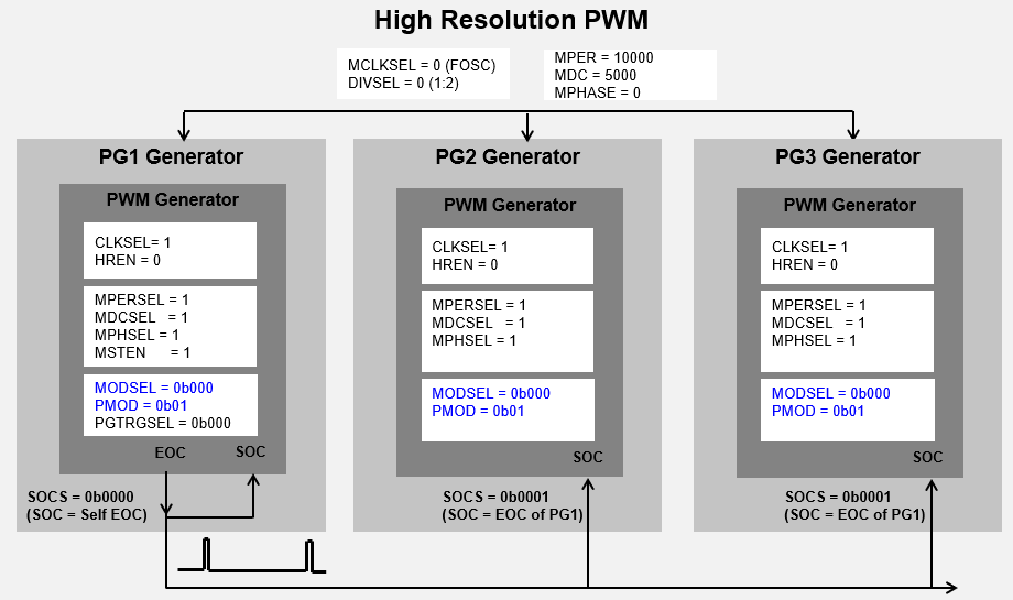
In this PWM scheme, only two switches are active at any given time. Of the two active phases, one high side and one low side switch is controlled with its phase’s corresponding PWM waveform, as shown below.

Since only one switch needs to be driven at a time on a given phase, independent PWM Output mode is used. The output override feature is used to turn off the other switches. A three-phase scheme is implemented using PWM Generator 1 (PG1) configured as Host and the other two PWM Generators (PG2 and PG3) configured as Client. PG1 is self-triggered, whereas PG2 and PG3 are triggered from PG1’s Start-of-Cycle (SOC). Enabling PG1 will start the system in a synchronized fashion.
Configuration Summary:
-
Independent Edge PWM mode
-
Independent Output mode
-
Master Period and Duty Cycle Used
-
Override State is drive low

1.2 PWM Switching Scheme 2
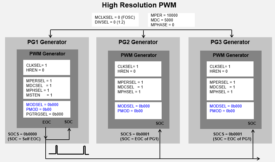
In this PWM scheme, three switches are used to control the two active phases. In a given sector, one active phase is driven with a complementary PWM waveform and the other active phase has only its low side driven high at 100% duty cycle, as shown in figure below. Like Scheme 1, overrides are used to control the outputs in each sector.

In this scheme, Complementary Output mode is used and overridden as needed in each sector. The same three-phase Host-Client synchronization technique is used as in Scheme 1.
Configuration Summary:
-
Independent Edge PWM mode
-
Complementary Output mode
-
Master Period and Duty Cycle Used
-
Override State is Dependent on Sector State
-
Dead time is applied to the Complementary PWM Signal

1.3 PWM Switching Scheme 3
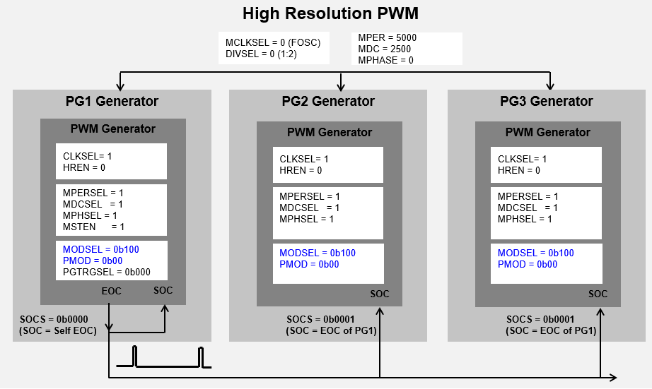
In this PWM scheme, four switches are driven in a given sector. Two pairs of complementary PWM outputs are applied to the two active phases. The inactive phase is overriden to low as needed, as shown below.

In this scheme, Center-Aligned PWM mode is used with dead time to prevent high current during switching transitions. The two active phases are driven 180 degrees out of phase to one another using the SWAP feature.
Configuration Summary:
- Center-Aligned PWM mode
- Complementary Output mode
- Master Period and Duty Cycle Used
- Override State is Dependent on Sector State
- Dead time is applied to the Complementary PWM Signal

2. SUGGESTED DEMONSTRATION REQUIREMENTS
2.1 MATLAB Model Required for the Demonstration
- MATLAB model can be cloned or downloaded as zip file from the Github repository (link).
2.2 Software Tools Used for Testing the MATLAB/Simulink Model
- MPLAB X IDE and IPE (v6.00)
- XC16 compiler (v2.00)
- MATLAB R2023a
- Required MATLAB add-on packages
- Simulink
- Simulink Coder
- MATLAB Coder
- Embedded Coder (v7.9)
- MPLAB Device blocks for Simulink (v3.50.35)
NOTE: The software used for testing the model during release is listed above. It is recommended to use the version listed above or later versions for building the model.
2.3 Hardware Tools Required for the Demonstration
- dsPIC33CK Curiosity Development Board (DM330030)
NOTE: All items listed under this section Hardware Tools Required for the Demonstration are available at microchip DIRECT.
3. HARDWARE SETUP
This section describes hardware setup required for the demonstration.
-
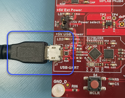
The board has an onboard programmer 'PICkit™ On Board (PKoBv4)', which can be used for programming or debugging the dsPIC33CK256MP508. To use the on-board programmer, connect a micro-USB cable between Host PC and Micro USB connector J7 provided on the dsPIC33CK Curiosity Development Board.
-
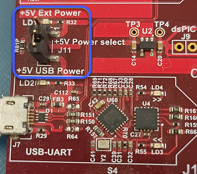
Make sure that the Jumper J11 is on the +5V USB Power side to power the dsPIC33CK Curiosity Development Board from Host PC through the USB cable.
-
Connect the PWM pins RB10, RB11, RB12, RB13, RB14 and RB15 to the oscilloscope to monitor the PWM signals.


4. BASIC DEMONSTRATION
Follow the instructions step-by-step, to set up and run the demo example:
-
Launch MATLAB (refer the section “2.2 Sofware Tools Used for Testing the MATLAB/Simulink Model").
-
Open the folder downloaded from the repository, in which MATLAB files are saved (refer the section "2.1 MATLAB Model Required for the Demonstration").
-
Double click on the Simulink model.
-
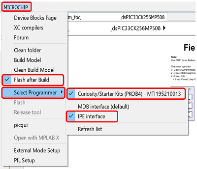
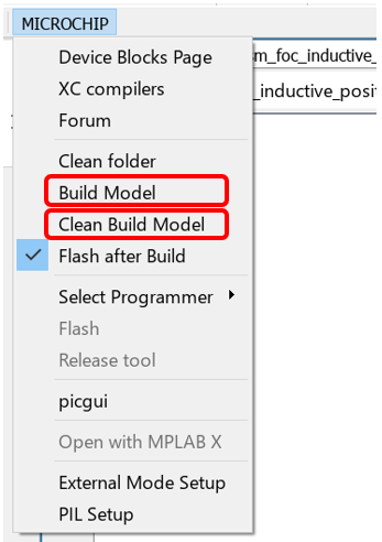
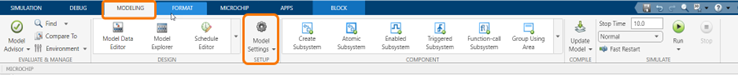
From this Simulink model an MPLAB X project can be generated. To generate the code from the Simulink model, go to the "MICROCHIP" tab, and enable the tabs shown in the figure below.
-
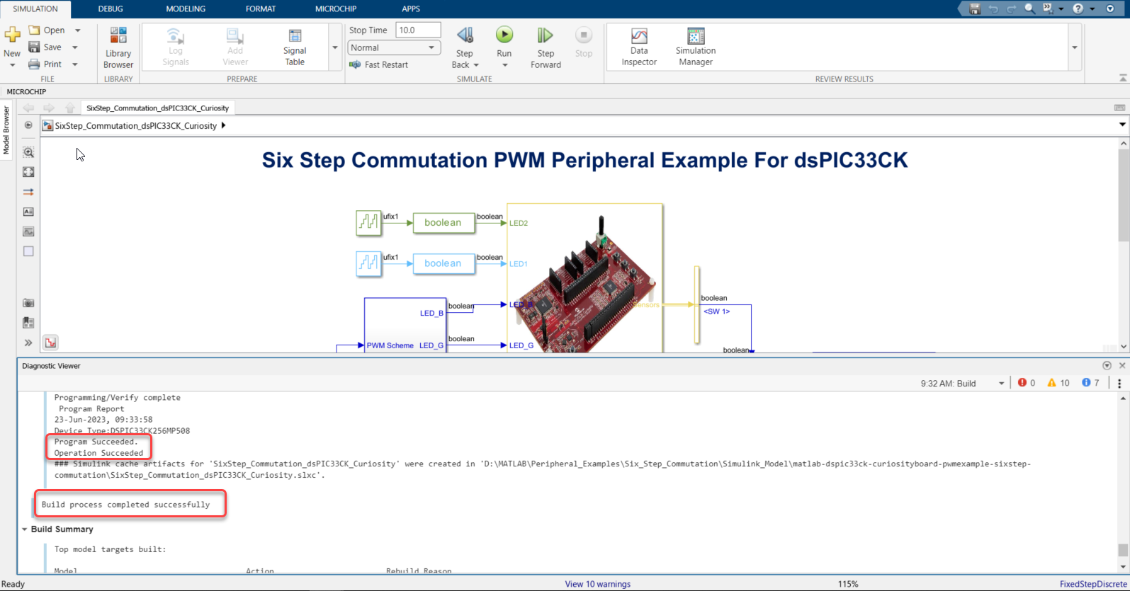
To generate the code and program the dsPIC, click on ‘Build Model’ or ‘Clean Build Model’ option under the “Microchip” tab. This will generate the MPLAB X project from the Simulink model and program the dsPIC33CK256MP508 device.
-
After completing the process, the ‘Operation Succeeded’ message will be displayed on the ‘Diagnostics Viewer’.
-
If the device is successfully programmed, LED1 and LED2 will be blinking.
-
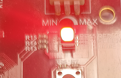
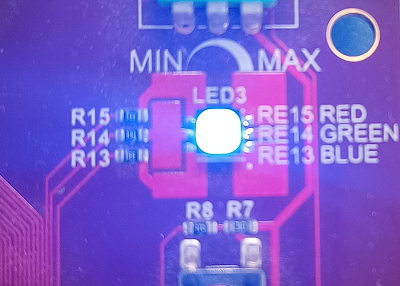
Press the push button SW1 to enable 'PWM Swithing Scheme 1' and 'RED LED' is turned ON to indicate it. Press the push button SW1 again to disable the PWMs.
-
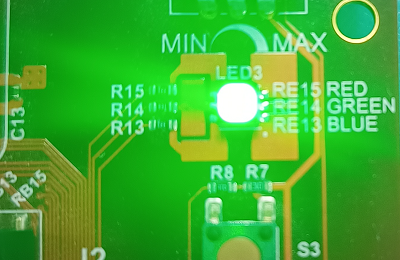
Press the push button SW1 to enable 'PWM Swithing Scheme 2' and 'GREEN LED' is turned ON to indicate it. Press the push button SW1 again to disable the PWMs.
-
Press the push button SW1 to enable 'PWM Swithing Scheme 3' and 'BLUE LED' is turned ON to indicate it. Press the push button SW1 again to disable the PWMs.


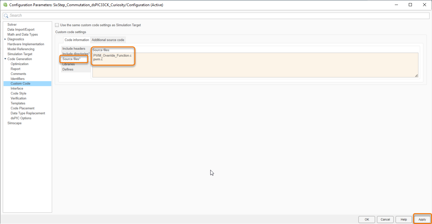
5. ADDING C SOURCE FILE TO THE SIMULINK MODEL:
The model incorporates a C source file, which has configurations required to implement various PWM switching schemes through override, swap and output mode features of the High Resolution PWM. Follow the steps below to add a C source file into the Simulink model.
-
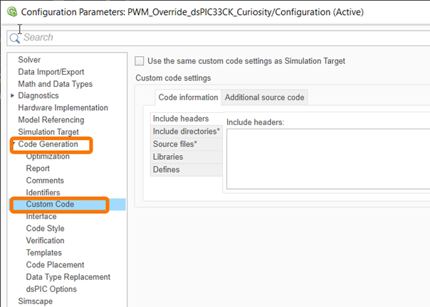
In the Modelling tab, click on the Model Settings.
-
Expand the Code Generation tab and click on the Custom Code.
-
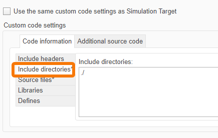
In the Include directories, add the path of the C source file. If the C source file is in the same directory as the Simulink model, then give “./”.
-
In the Source files tab, enter the C source file name which needs to be included. Then click Apply.


6. REFERENCES:
For more information, refer to the following documents or links.
Cite As
Microchip Support Team (2026). PWM Peripheral Example: Six Step Commutation Using dsPIC33CK (https://github.com/microchip-pic-avr-examples/matlab-dspic33ck-curiosityboard-pwmexample-sixstep-commutation/releases/tag/1.0.1), GitHub. Retrieved .
General Information
- Version 1.0.1 (4.94 MB)
-
 View License on GitHub
MATLAB Release Compatibility
- Compatible with R2023a and later releases
Platform Compatibility
- Windows
- macOS
- Linux
| Version | Published | Release Notes | Action |
|---|---|---|---|
| 1.0.1 | See release notes for this release on GitHub: https://github.com/microchip-pic-avr-examples/matlab-dspic33ck-curiosityboard-pwmexample-sixstep-commutation/releases/tag/1.0.1 |
||
| 1.0.0 |