Compressor
Dynamic range compressor
Libraries:
Audio Toolbox /
Dynamic Range Control
Description
The Compressor block performs dynamic range compression independently across each input channel. Dynamic range compression attenuates the volume of loud sounds that cross a given threshold. The block uses specified attack and release times to achieve a smooth applied gain curve.
Examples
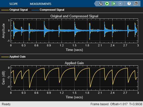
Suppress Loud Sounds
Use the Compressor block to suppress loud sounds and visualize the applied compression gain.
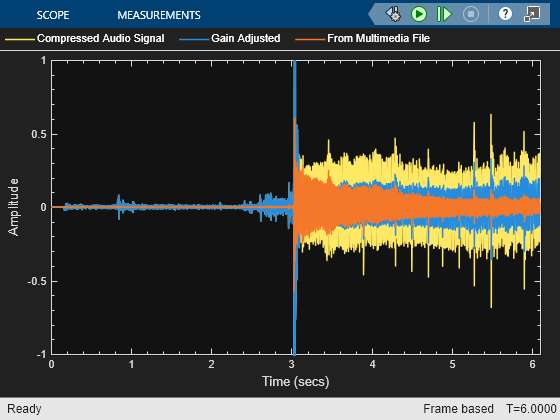
Trigger Gain Control Based on Loudness Measurement
This model enables you to apply dynamic range compression to an audio signal while staying inside a preset loudness range. In this model, a Compressor block increases the loudness and decreases the dynamic range of an audio signal. A Loudness Meter block calculates the momentary loudness of the compressed audio signal. If momentary loudness crosses a -23 LUFS threshold, an enabled subsystem applies gain to lower the corresponding level of the audio signal.
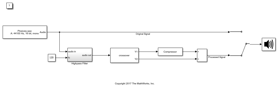
Diminish Plosives from Speech
This model minimizes the plosives of a speech signal by applying highpass filtering and low-band compression.
Ports
Input
Output
Parameters
Block Characteristics
Data Types |
|
Direct Feedthrough |
|
Multidimensional Signals |
|
Variable-Size Signals |
|
Zero-Crossing Detection |
|
Algorithms
The Compressor block processes a signal frame by frame and element by element.
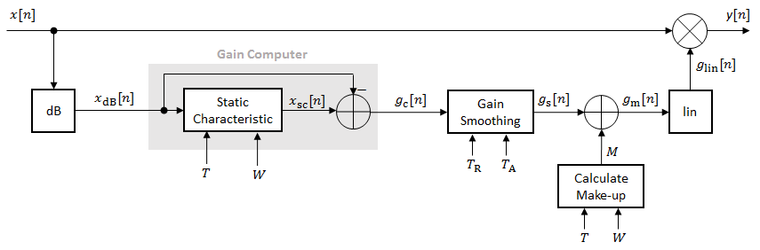
The N-point signal, x[n], is converted to decibels:
xdB[n] passes through the gain computer. The gain computer uses the static compression characteristic of the Compressor block to attenuate gain that is above the threshold.
If you specified a soft knee, the gain computer has the following static characteristic:
where T is the threshold, R is the compression ratio, and W is the knee width.
If you specified a hard knee, the gain computer has the following static characteristic:
The computed gain, gc[n], is calculated as
gc[n] is smoothed using specified attack and release time parameters:
The attack time coefficient, α A, is calculated as
The release time coefficient, α R, is calculated as
T A is the attack time period, specified by the Attack time (s) parameter. TR is the release time period, specified by the Release time (s) parameter. Fs is the input sampling rate, specified by the Inherit sample rate from input or the Input sample rate (Hz) parameter.
If Make-up gain (dB) is set to
Auto, the make-up gain is calculated as the negative of the computed gain for a 0 dB input:Given a steady-state input of 0 dB, this configuration achieves a steady-state output of 0 dB. The make-up gain is determined by the Threshold (dB), Ratio, and Knee width (dB) parameters. It does not depend on the input signal.
The make-up gain, M, is added to the smoothed gain, gs[n]:
The calculated gain in dB, gdB[n], is translated to a linear domain:
The output of the dynamic range compressor is given as
References
[1] Giannoulis, Dimitrios, Michael Massberg, and Joshua D. Reiss. "Digital Dynamic Range Compressor Design –– A Tutorial And Analysis." Journal of Audio Engineering Society. Vol. 60, Issue 6, 2012, pp. 399–408.
Extended Capabilities
Version History
Introduced in R2016a