Configure Client-Server Communication AUTOSAR Architectures with System Composer
You model AUTOSAR client-server communication in Simulink® by creating client-server interfaces in the AUTOSAR Dictionary, and mapping them to Simulink functions and client and server ports in a Simulink model. Optionally, you can create direct connections between client components and server components if you have System Composer™ software.
In this example you will,
Create AUTOSAR client-server interfaces, operations, and arguments and map them to your Simulink models.
Optionally, link AUTOSAR client and server models to software components in a System Composer architecture model. (Requires System Composer)
This example assumes knowledge on how to create and configure AUTOSAR software components for the AUTOSAR Classic Platform. For more information on creating such components, see Create AUTOSAR Software Component.
Connect Architecture Components Using Client-Server Ports
Create a new AUTOSAR architecture model.
Add three Classic Component blocks to the canvas and name them
SensorManager,Sensor, andMonitor.Add two server ports to the
SensorManagerComponent block, namedFrontSensorConfig, andRearSensorConfig.Select the edge of the block and pause over the inport.
Select Server from the options that appear.

In a similar way, add a client port named
SensorConfigto theSensorComponent block.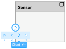
Add an output port named
SensorDatato theSensorComponent block.Select the
SensorComponent block and open the Property Inspector. From the Kind list, selectSensorActuator.
Add two input ports named
FrontSensorandRearSensorand one output port namedSensorDatato theMonitorComponent block.Draw a signal out of
SensorDatathat exits the architecture on the edge of the canvas.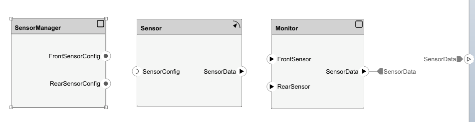
Assign Service Interface to Client-Server Ports
To define client-server interfaces you can assign service interfaces stored in the Architectural Data section of a linked data dictionary to client server ports in an architecture model.
In the modeling toolstrip of your AUTOSAR architecture, navigate to the Modeling tab and in the Design section, select Architectural Data Editor to open the Architectural Data Editor.
In the Architectural Data Editor select New to create a new data dictionary. Name the data dictionary
ProximityInterfaces.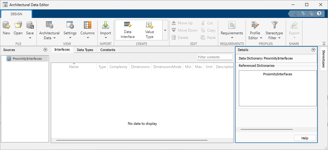
Add a service interface by selecting Service Interface from the Create section of the Architectural Data Editor toolstrip. Name the interface
SensorConfig.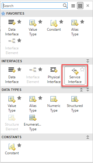
Edit the function of the
SensorConfigservice interface by double-clicking the function and typing in the cell. Replace the function with[enabled,scanDepth,blkSize] = getSnsrCfg().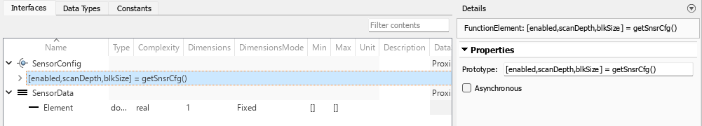
Add a data interface to the dictionary and name it
SensorData.Save the dictionary, and then close the Architectural Data Editor and return to the architecture canvas.
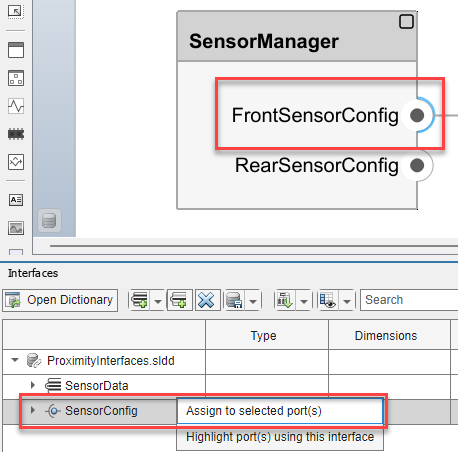
On the Modeling tab of the toolstrip, in the Design section, select Link Existing Dictionary. Select the
ProximityInterfaces.slddin the File name list and clock open. The Interface Editor appears below the canvas.Assign the interfaces to the ports of the architecture model by using the Interface Editor (System Composer).
Expand the
ProximityInterfaces.sldddictionary.Select the
FrontSensorConfigport, and then right-click theSensorConfiginterface in the Interface Editor.Click
Assign to selected port(s)to assignSensorConfigas the interface for theFrontSensorConfigport.Similarly assign the
SensorConfigservice interface as the interface for theRearSensorConfigserver port.Assign the
SensorDatadata interface to theSensorDataoutput ports on theSensorandMonitorComponent blocks.Assign the
SensorDatadata interface to the input portsFrontSensorandRearSensoron theMonitorComponent block. Save the model.
Connect the ports of the Component blocks.
Connect the
FrontSensorConfigserver port to theSensorConfigclient port on theSensorComponent block.Connect the
SensorDataoutput port of theSensorComponent block to theFrontSensorinput port on theMonitorComponent block.
Right-click the
SensorComponent block and select Create Simulink Behavior. In the Create Simulink Model dialog box, click OK and Simulink creates a model to represent the client-server communication structure. Create Simulink behavior in the same way for the remaining Component blocks.Duplicate the
SensorComponent block.
Rename the original
SensorComponent block asFrontProximitySensor, and rename the newSensor1Component block asRearProximitySensor.Connect the server ports of the Component blocks.
Connect the
RearSensorConfigserver port to theSensorConfigclient port on theRearProximitySensorComponent block.Connect the output port
SensorDataof theRearProximitySensorComponent block to theRearSensorinput port on theMonitorComponent block.
Save and export the architecture.
Inspect the exported ARXML. Server ports are tagged by
PROVIDER-IREFand client ports are tagged byREQUESTER-IREF.<SHORT-NAME>SensorManager_FrontSensorConfig_FrontProximitySnsr_SensorConfig</SHORT-NAME> <PROVIDER-IREF> <CONTEXT-COMPONENT-REF DEST="SW-COMPONENT-PROTOTYPE">/Components/myWorkflowCSServiceArch/SensorManager</CONTEXT-COMPONENT-REF> <TARGET-P-PORT-REF DEST="P-PORT-PROTOTYPE">/Components/SensorManager/FrontSensorConfig</TARGET-P-PORT-REF> </PROVIDER-IREF> <REQUESTER-IREF> <CONTEXT-COMPONENT-REF DEST="SW-COMPONENT-PROTOTYPE">/Components/myWorkflowCSServiceArch/FrontProximitySnsr</CONTEXT-COMPONENT-REF> <TARGET-R-PORT-REF DEST="R-PORT-PROTOTYPE">/Components/FrontProximitySnsr/SensorConfig</TARGET-R-PORT-REF> </REQUESTER-IREF>The service interfaces are tagged with
CLIENT-SERVER-INTERFACEand contain their operations and arguments.<CLIENT-SERVER-INTERFACE UUID="..."> <SHORT-NAME>SensorConfig</SHORT-NAME> <IS-SERVICE>false</IS-SERVICE> <OPERATIONS> <CLIENT-SERVER-OPERATION UUID="..."> <SHORT-NAME>getSnsrCfg</SHORT-NAME> <ARGUMENTS> <ARGUMENT-DATA-PROTOTYPE UUID="..."> <SHORT-NAME>enabled</SHORT-NAME> <CATEGORY>VALUE</CATEGORY> <SW-DATA-DEF-PROPS> <SW-DATA-DEF-PROPS-VARIANTS> <SW-DATA-DEF-PROPS-CONDITIONAL> <SW-CALIBRATION-ACCESS>READ-ONLY</SW-CALIBRATION-ACCESS> <SW-IMPL-POLICY>STANDARD</SW-IMPL-POLICY> </SW-DATA-DEF-PROPS-CONDITIONAL> </SW-DATA-DEF-PROPS-VARIANTS> </SW-DATA-DEF-PROPS> <TYPE-TREF DEST="IMPLEMENTATION-DATA-TYPE">/DataTypes/float64</TYPE-TREF> <DIRECTION>OUT</DIRECTION> </ARGUMENT-DATA-PROTOTYPE> <ARGUMENT-DATA-PROTOTYPE UUID="..."> <SHORT-NAME>scanDepth</SHORT-NAME> <CATEGORY>VALUE</CATEGORY> <SW-DATA-DEF-PROPS> <SW-DATA-DEF-PROPS-VARIANTS> <SW-DATA-DEF-PROPS-CONDITIONAL> <SW-CALIBRATION-ACCESS>READ-ONLY</SW-CALIBRATION-ACCESS> <SW-IMPL-POLICY>STANDARD</SW-IMPL-POLICY> </SW-DATA-DEF-PROPS-CONDITIONAL> </SW-DATA-DEF-PROPS-VARIANTS> </SW-DATA-DEF-PROPS> <TYPE-TREF DEST="IMPLEMENTATION-DATA-TYPE">/DataTypes/float64</TYPE-TREF> <DIRECTION>OUT</DIRECTION> </ARGUMENT-DATA-PROTOTYPE> <ARGUMENT-DATA-PROTOTYPE UUID="..."> <SHORT-NAME>blkSize</SHORT-NAME> <CATEGORY>VALUE</CATEGORY> <SW-DATA-DEF-PROPS> <SW-DATA-DEF-PROPS-VARIANTS> <SW-DATA-DEF-PROPS-CONDITIONAL> <SW-CALIBRATION-ACCESS>READ-ONLY</SW-CALIBRATION-ACCESS> <SW-IMPL-POLICY>STANDARD</SW-IMPL-POLICY> </SW-DATA-DEF-PROPS-CONDITIONAL> </SW-DATA-DEF-PROPS-VARIANTS> </SW-DATA-DEF-PROPS> <TYPE-TREF DEST="IMPLEMENTATION-DATA-TYPE">/DataTypes/float64</TYPE-TREF> <DIRECTION>OUT</DIRECTION> </ARGUMENT-DATA-PROTOTYPE> </ARGUMENTS> </CLIENT-SERVER-OPERATION> </OPERATIONS> </CLIENT-SERVER-INTERFACE>
See Also
Architectural Data Editor | Interface Editor (System Composer)