apskdemod
Amplitude phase shift keying (APSK) demodulation
Description
Z = apskdemod(Y,M,radii)Y, based on the
specified number of constellation points per PSK ring, M, and
the radius of each PSK ring, radii. For a description of APSK
demodulation, see APSK Hard Demodulation and APSK Soft Demodulation.
Note
apskdemod specifically applies to multiple ring PSK
constellations. For a single ring PSK constellation, use pskdemod.
Z = apskdemod(Y,M,radii,phaseoffset)
Z = apskdemod(___,Name=Value)apskdemod(Y,M,PlotConstellation=true) demodulates using
constellation points per ring specified in input vector M and
plots the constellation. Specify name-value arguments after all other input
arguments.
Examples
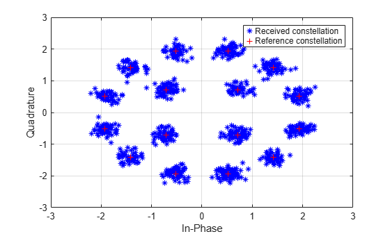
Demodulate a 16-APSK signal that has an unequal number of constellation points on each circle. Plot the received constellation.
Define vectors for modulation order and PSK ring radii. Generate random 16-ary data symbols.
M = [4 12];
radii = [1 2];
modOrder = sum(M);

x = randi([0 modOrder-1],1000,1);
Apply APSK modulation to the data.
txSig = apskmod(x,M,radii);
Pass the modulated signal through a noisy channel.
snr = 20; % dB
rxSig = awgn(txSig,snr,'measured');
Plot the transmitted (reference) signal points and the noisy received signal points.
plot(rxSig,'b*')
hold on
grid
plot(txSig,'r+')
xlim([-3 3])
ylim([-3 3])
xlabel('In-Phase')
ylabel('Quadrature')
legend('Received constellation','Reference constellation')
Demodulate the received signal and compare to the input data.
z = apskdemod(rxSig,M,radii);
isequal(x,z)
ans = logical
   0
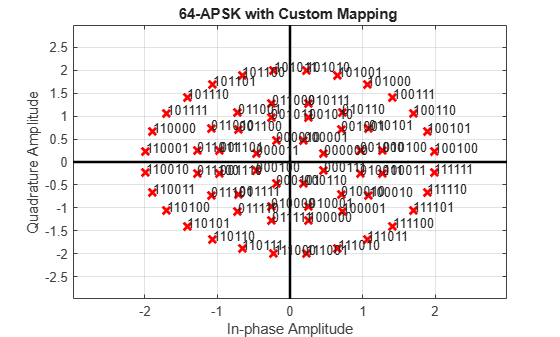
Demodulate a 64-APSK signal with custom symbol mapping. Compute hard decision bit output and verify that the input matches the output.
Define vectors for modulation order and PSK ring radii. Generate 100 symbols of random bit input.
M = [8 12 16 28]; % 4-PSK circles
modOrder = sum(M);
radii = [0.5 1 1.3 2];
x = randi([0 1],100*log2(modOrder),1);
Create a custom symbol mapping vector of binary mapping.
cmap = 0:63;
Modulate the data and plot the constellation.
y = apskmod(x,M,radii, ...
        SymbolMapping=cmap, ...
        InputType='bit', ...
        PlotConstellation=true);
Demodulate the received signal.
z = apskdemod(y,M,radii,SymbolMapping=cmap,OutputType='bit');Verify that the demodulated signal is equal to the original data.
isequal(x,z)
ans = logical
   1
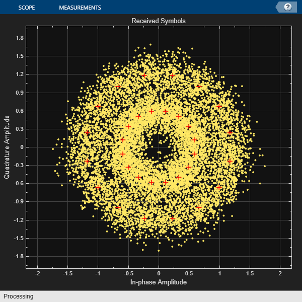
Demodulate a 32-APSK signal and calculate soft bits.
Define vectors for modulation order and PSK ring radii. Generate 10000 symbols of random bit data.
M = [16 16];
modOrder = sum(M);
radii = [0.6 1.2];
numSym = 10000;
x = randi([0 1], numSym*log2(modOrder),1);
Generate a reference constellation. Create a constellation diagram object.
refAPSK = apskmod(0:modOrder-1,M,radii);
constDiagAPSK = comm.ConstellationDiagram( ...
    ReferenceConstellation=refAPSK, ...
    Title='Received Symbols', ...
    XLimits=[-2 2], ...
    YLimits=[-2 2]);
Modulate the data.
txSig = apskmod(x,M,radii,InputType='bit');
sigPow = var(txSig);
Pass the signal through a noisy channel.
snr = 15;
rxSig = awgn(txSig,snr,sigPow,'linear');
Plot the reference and received constellation symbols.
constDiagAPSK(rxSig)
Demodulate the signal and compute soft bits.
z = apskdemod(rxSig,M,radii, ...
    OutputType='approxllr', ...
    NoiseVariance=sigPow/snr);
Input Arguments
Name-Value Arguments
Output Arguments
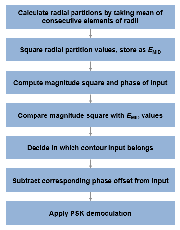
Algorithms
References
[1] Sebesta, J. “Efficient Method for APSK Demodulation.” Selected Topics on Applied Mathematics, Circuits, Systems, and Signals (P. Pardalos, N. Mastorakis, V. Mladenov, and Z. Bojkovic, eds.). Vouliagmeni, Athens, Greece: WSEAS Press, 2009.
[2] Liu, Z., Q. Xie, K. Peng, and Z. Yang. "APSK Constellation with Gray Mapping." IEEE Communications Letters. Vol. 15, Number 12, December 2011, pp. 1271–1273.
Extended Capabilities
Version History
Introduced in R2018a