comm.ConstellationDiagram
Display and analyze input signals in IQ-plane
Description
The comm.ConstellationDiagram
System object™ displays real- and complex-valued floating- and fixed-point signals in the IQ
plane. Specifically, the IQ-plane displays the in-phase and quadrature components of modulated
signals on the real and imaginary axis of an xy-plot. Use this System object to perform qualitative and quantitative analysis on modulated single-carrier
signals.
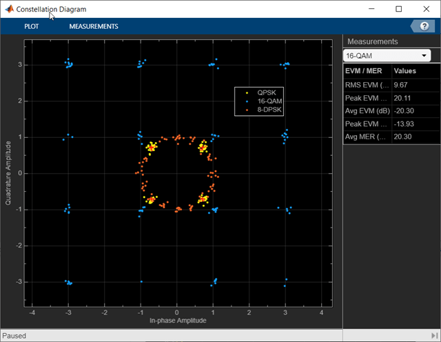
In the Constellation Diagram window, you can:
Input and plot multiple signals on a single constellation diagram. To define a reference constellation for each input signal, use the
ReferenceConstellation
property.Select signals in the legend to toggle visibility of individual channels. To display the legend, use the
ShowLegend
property. For a multichannel signal, specify the input as a matrix with individual signals defined in the columns of the matrix.Display calculated error vector magnitude (EVM) and modulation error ratio (MER) measurements for individual signals. To view and configure the measurements, select EVM/MER on the Measurements tab. When multiple signals are input, you can select which signal to use for measurements in the Channel section.
To display constellation diagrams for input signals:
Create the
comm.ConstellationDiagram
object and set its properties.Call the object with arguments, as if it were a function.
To learn more about how System objects work, see What Are System Objects?
Creation
Description
returns a constellation diagram System object that displays real- and complex-valued floating- and fixed-point signals in
the IQ plane.constdiag
= comm.ConstellationDiagram
sets properties using one or more name-value arguments. For example,
constdiag
= comm.ConstellationDiagram(Name
=Value
)comm.ConstellationDiagram(SamplesPerSymbol=10)
specifies 10 samples
for each plotted symbol.
Properties
Unless otherwise indicated, properties are nontunable, which means you cannot change their
values after calling the object. Objects lock when you call them, and the
release
function unlocks them.
If a property is tunable, you can change its value at any time.
For more information on changing property values, see System Design in MATLAB Using System Objects.
Name
— Title of Constellation Diagram window
'Constellation Diagram'
(default) | character vector | string scalar
Title of the Constellation Diagram window, specified as a character vector or string scalar.
Tunable: Yes
Data Types: char
| string
ShowTrajectory
— Option to plot signal trajectory
false
or 0
(default) | true
or 1
Option to plot the signal trajectory, specified as a logical 0
(false
) or 1
(true
). Setting
this property to true
displays the trajectory between constellation
points for the plotted signals. To view the signal trajectory, select
Trajectory on the Plot tab.
Tunable: Yes
Data Types: logical
ShowReferenceConstellation
— Option to display reference constellation
true
or 1
(default) | false
or 0
Option to display the reference constellation, specified as a logical
1
(true
) or 0
(false
).
Tunable: Yes
Data Types: logical
EnableMeasurements
— Option to calculate and display EVM and MER measurements
false
or 0
(default) | true
or 1
Option to calculate and display the EVM and MER measurements, specified as a logical
0
(false
) or 1
(true
).
Tunable: Yes
Data Types: logical
NumInputPorts
— Number of input signals
1
(default) | integer in the range [1, 20]
Number of input signals, specified as an integer in the range [1, 20]. Each input signal, whether it is a multichannel signal or a single channel signal, becomes a separate channel in the scope.
The total number of channels cannot exceed 20. When you specify multichannel input signals, the maximum number of input signals is limited by the total number of input channels that you define.
When you call the object, the number of inputs that you specify must equal the value of this property.
Tips
To define ReferenceConstellation
values for multiple input signals, you must first
set the NumInputPorts
value.
Data Types: double
SamplesPerSymbol
— Number of samples used to represent each symbol
1
(default) | positive integer
Number of samples used to represent each symbol, specified as a positive integer. The signal is downsampled by the value of this property before it is plotted.
Tunable: Yes
Data Types: double
SampleOffset
— Number of samples to skip before plotting points
0
(default) | nonnegative integer
Number of samples to skip before plotting points, specified as a nonnegative integer
less than the SamplesPerSymbol
property
value. This value specifies the number of samples to skip when SamplesPerSymbol
is
greater than 1.
Tunable: Yes
Data Types: double
SymbolsToDisplaySource
— Source of symbols to display
'Input frame length'
(default) | 'Property'
Source of symbols to display, specified as one of these values.
'Input frame length'
— The number of symbols to display is equal to the input frame length divided by theSamplesPerSymbol
property value.'Property'
— TheSymbolsToDisplay
property specifies the maximum number of symbols to display.
Tunable: Yes
Data Types: char
| string
SymbolsToDisplay
— Maximum number of symbols to display
256
(default) | positive integer
Maximum number of symbols to display, specified as a positive integer. Use this property to limit the maximum number of symbols that the constellation diagram displays when you input long signals. The object plots the most recently received symbols.
Tunable: Yes
Dependencies
To enable this property, set SymbolsToDisplaySource
to 'Property'
.
Data Types: double
ColorFading
— Option to add color fading effect
false
or 0
(default) | true
or 1
Option to add color fading effect, specified as a logical 0
(false
) or 1
(true
). When you
set this property to true
, the points in the display fade as the
interval of time after they are first plotted increases. This animation resembles an
oscilloscope display.
Tunable: Yes
Data Types: logical
XLimits
— x-axis limits
[-1.375 1.375]
(default) | two-element row vector
x-axis limits, specified as a two-element row vector of the form [xmin xmax]. The first element is the minimum x-axis value, and the second element is the maximum x-axis value.
Tunable: Yes
Data Types: double
YLimits
— y-axis limits
[-1.375 1.375]
(default) | two-element row vector
y-axis limits, specified as a two-element row vector of the form [ymin ymax]. The first element is the minimum y-axis value, and the second element is the maximum y-axis value.
Tunable: Yes
Data Types: double
XLabel
— x-axis label
'In-phase Amplitude'
(default) | character vector | string scalar
x-axis label, specified as a character vector or string scalar.
Tunable: Yes
Data Types: char
| string
YLabel
— y-axis label
'Quadrature Amplitude'
(default) | character vector | string scalar
y-axis label, specified as a character vector or string scalar.
Tunable: Yes
Data Types: char
| string
Title
— Plot title
''
(default) | character vector | string scalar
Plot title, specified as a character vector or string scalar.
Tunable: Yes
Data Types: char
| string
ShowLegend
— Option to display legend
false
or 0
(default) | true
or 1
Option to display the legend, specified as a logical 0
(false
) or 1
(true
). The
names listed in the legend are the signal names specified by the ChannelNames
property. The
legend does not display until you call the object with an input signal.
In the scope legend, click a signal name to toggle the signal visibility in the scope.
Tunable: Yes
Data Types: logical
ChannelNames
— Names for input channels
{''}
(default) | cell array of strings or character vectors
Names for the input channels, specified as a cell array of strings or character
vectors. If you do not specify names, the object labels the channels as Channel
1
, Channel 2
, etc.
These names appear in the legend, the Measurements tab, and the Measurements Setting pane.
Example: {'8-QAM','8-PSK'}
specifies the names for two input
channels to 8-QAM
and 8-PSK
.
Tunable: Yes
Data Types: cell
ShowGrid
— Option to show grid
true
or 1
(default) | false
or 0
Option to show grid on the constellation diagram, specified as a logical
1
(true
) or 0
(false
).
Tunable: Yes
Data Types: logical
ShowTicks
— Option to show tick labels
false
or 0
(default) | true
or 1
Option to show tick labels on the constellation diagram axes, specified as a logical
0
(false
) or 1
(true
).
Tunable: Yes
Data Types: logical
Position
— Scope window position and size
600-by-600 pixel window at center of screen (default) | four-element row vector
Scope window position and size in pixels, specified as a four-element row vector of the form [left bottom width height]. The first two elements in the vector indicate the location of the lower-left corner, and the second elements two specify the size of the window. The default value for the location depends on the screen resolution.
Tunable: Yes
Data Types: double
ReferenceConstellation
— Reference constellations
[0.7071+0.7071i -0.7071+0.7071i -0.7071-0.7071i
0.7070-0.7071i]
(default) | row vector | cell array
Reference constellations for the input signals, specified as a row vector or cell array of vectors defining the ideal constellation points for each input signal. Input signals can be single channel or multichannel. You can define one reference constellation for each input signal.
When you specify a row vector, the values apply for all input signals.
When you specify a cell array, you can specify individual reference constellations for each input signal.
The EVM and MER measurements use the specified reference constellation to calculate the signal quality of the modulated input signal. For more information about the signal quality measurements, see EVM and MER Measurements.
Tunable: Yes
Dependencies
To define ReferenceConstellation
values for multiple input
signals, you must first set the NumInputPorts
value.
Data Types: double
Complex Number Support: Yes
ReferenceColor
— Color for reference display constellation
[1 0 0]
(red) (default) | three-element row vector | cell array
Color for reference display constellation, specified as a three-element row vector indicating RGB component colors or as a cell array containing RGB component colors for each input signal.
Tunable: Yes
Data Types: double
ReferenceMarker
— Marker for reference constellation display
'+'
(default) | 'o'
| '*'
| '.'
| 'x'
| ...
Marker for the reference constellation display, specified as one of the values listed in this table.
Marker | Description | Resulting Marker |
---|---|---|
"o" | Circle |
|
"+" | Plus sign |
|
"*" | Asterisk |
|
"." | Point |
|
"x" | Cross |
|
"_" | Horizontal line |
|
"|" | Vertical line |
|
"square" | Square |
|
"diamond" | Diamond |
|
"^" | Upward-pointing triangle |
|
"v" | Downward-pointing triangle |
|
">" | Right-pointing triangle |
|
"<" | Left-pointing triangle |
|
"pentagram" | Pentagram |
|
"hexagram" | Hexagram |
|
"none" | No markers | Not applicable |
Tunable: Yes
MeasurementInterval
— Window length for EVM and MER measurements
'Current display'
(default) | 'All displays'
| ...
Window length for the EVM and MER measurements, specified as 'Current
display'
, 'All displays'
, or an integer in the range [2,
SymbolsToDisplay
].
For more information, see EVM and MER Measurements.
Tunable: Yes
Data Types: char
| string
| double
EVMNormalization
— EVM normalization method
'Average constellation power'
(default) | 'Peak constellation power'
EVM normalization method, specified as 'Average constellation
power'
or 'Peak constellation power'
. For more
information, see EVM and MER Measurements.
Tunable: Yes
Usage
Description
constdiag(
displays
up to N signals in one constellation diagram, where
N is the signal1, ..., signalN
)NumInputPorts
property value.
Input Arguments
signal1, ..., signalN
— Signals (as separate arguments)
column vectors | matrices
Signals, specified as separate arguments of Nsym-by-1 column vectors or Nsym-by-Nchannel matrices. Nsym is the number of symbols, and Nchannel is the number of input signal channels. Signals can have different data types and dimensions.
You must specify N input arguments, where N
is the NumInputPorts
property value. You can visualize up to 20 individual or
collective signal channels in the constellation diagram. For example, if you create a
two-channel signal for every input, then you can define up to 10 input arguments.
This object accepts variable-size inputs. After the object is locked, you can change the size of each input channel, but you cannot change the number of channels. For more information, see Variable-Size Signal Support with System Objects.
Example: [sig1_1,sig1_2],sig2
specifies two signals, provided
that sig1_1
, sig1_2
, and sig2
are single channel column vector signals. The first,
[sig1_1,sig1_2]
, specifies a two-channel signal (constructed by
concatenating two column vectors into a matrix). The second signal,
sig2
, specifies a single channel.
Data Types: double
Complex Number Support: Yes
Object Functions
To use an object function, specify the
System object as the first input argument. For
example, to release system resources of a System object named obj
, use
this syntax:
release(obj)
Specific to Scopes
Examples
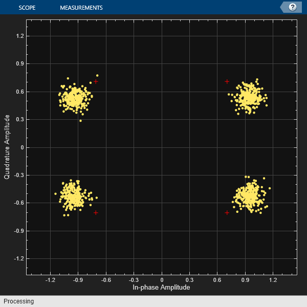
Display Amplitude-Imbalanced QPSK Constellation
QPSK-modulate random data symbols and apply an amplitude imbalance to the signal. Pass the signal through a noisy channel. Display the resultant constellation.
Create a constellation diagram System object. Because the default reference constellation for the object is QPSK, setting additional properties is not necessary.
constDiagram = comm.ConstellationDiagram;
Generate random data symbols, and then apply QPSK modulation.
data = randi([0 3],1000,1); modData = pskmod(data,4,pi/4);
Apply an amplitude imbalance to the modulated signal.
txSig = iqimbal(modData,5);
Pass the transmitted signal through an AWGN channel, and then display the constellation diagram. The data points shift from their ideal locations.
rxSig = awgn(txSig,20); constDiagram(rxSig)
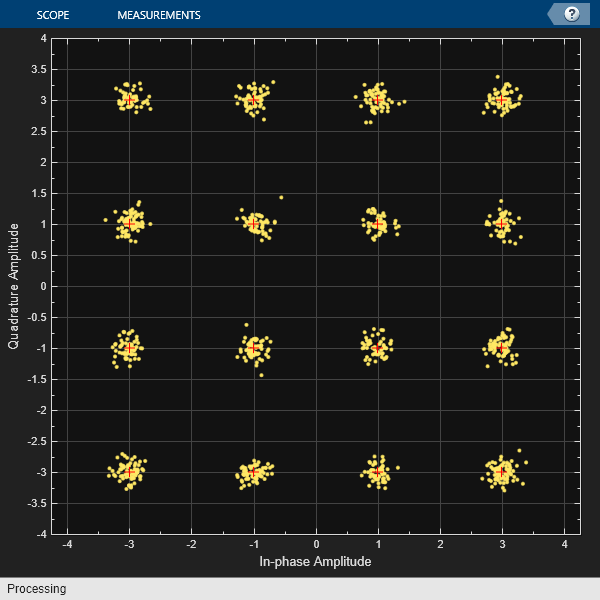
Display 16-QAM Constellation
Apply 16-QAM modulation, transmit data using an AWGN channel, and display the signal constellation.
Create a 16-QAM reference constellation.
M = 16; refC = qammod(0:M-1,M);
Create a constellation diagram System object, specifying the constellation reference points and axes limits.
constDiagram = comm.ConstellationDiagram('ReferenceConstellation',refC, ... 'XLimits',[-4 4],'YLimits',[-4 4]);
Generate random 16-ary data symbols.
data = randi([0 M-1],1000,1);
Apply 16-QAM modulation.
sym = qammod(data,M);
Pass the modulated signal through an AWGN channel.
rcv = awgn(sym,15);
Display the constellation diagram.
constDiagram(rcv)
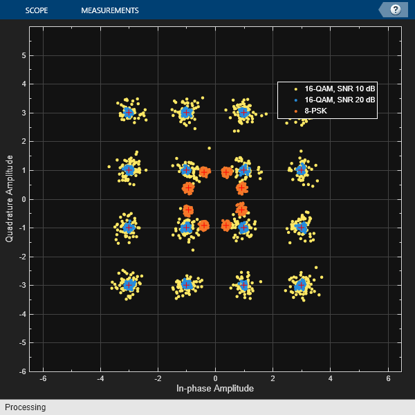
Display Constellation of Multi-Input Signals
Display the constellation of multi-input and multichannel modulated signals. Plot a multichannel signal with two 16-QAM signals for the first input and one 8-PSK signal for the second input.
Create a 16-QAM and an 8-PSK reference constellation.
M = 16; refQAM = qammod(0:M-1,M); S = 8; refPSK = pskmod(0:S-1,S,pi/8);
Create a constellation diagram System object, specifying reference constellations for the two input signals. The object applies a single reference constellation for all the channels of an individual multichannel signal input, but separate input signals can specify separate reference constellations.
constDiag = comm.ConstellationDiagram(2, ... 'ReferenceConstellation',{refQAM,refPSK}, ... 'ShowLegend',true, ... 'XLimits',[-6 6],'YLimits',[-6 6], ... 'ChannelNames', ... {'16-QAM, SNR 10 dB','16-QAM, SNR 20 dB','8-PSK'});
Generate random data symbols, modulate the symbols, and add AWGN with two different SNRs to yield two received signals. Use SNR values of 10 and 20 dB.
d = randi([0 M-1],1000,1); dQAM = qammod(d,M); rcv1_1 = awgn(dQAM,10); rcv1_2 = awgn(dQAM,20); d = randi([0 S-1],1000,1); dPSK = pskmod(d,S,pi/8); rcv2 = awgn(dPSK,20);
For the first input, create a multichannel signal by concatenating the two received 16-QAM signals. For the second input uses a single channel 8-PSK signal.
Display the constellation diagram of the multi-input and multichannel signals.
constDiag([rcv1_1,rcv1_2],rcv2);
More About
EVM and MER Measurements
The Measurements pane displays the EVM and MER signal quality measurement settings and the calculation results for the specified signal channel.
EVM — An error vector is a vector in the IQ plane from the ideal constellation point to the actual point at the receiver. The EVM calculations include root mean square (RMS), peak, and average values.
You can normalize the EVMRMS and EVMAverage calculations by the average or peak constellation power method as computed using these algorithms.
EVM Normalization Method Algorithm Average constellation power EVMRMS, in percent, for average constellation power normalization:
Peak constellation power EVMRMS, in percent, for peak constellation power normalization:
The Measurements pane shows the RMS and peak EVM in percent and the average and peak EVM decibels for the selected input channel. The EVM in decibels is computed as EVM (dB) = 10 ‑ log10(EVMMS) = 20 ‑ log10(EVMRMS), where:
Ik is the in-phase value of the kth symbol in the input vector.
Qk is the quadrature phase value of the kth symbol in the input vector.
Ik and Qk represent ideal (reference) symbol values. and represent measured (received) symbol values.
N is the input vector length.
Pavg is the value for average constellation power.
Pmax is the value for peak constellation power.
The maximum EVM value in a vector is where k is the kth symbol in a vector of length N.
MER — MER is the ratio of the average power of the transmitted signal to the average power of the error vector. The Measurements pane indicates average MER measurement result in decibels for the selected signal channel.
MER is a measure of the SNR in a modulated signal, calculated in dB. The MER over N symbols is
where:
Ik is the in-phase value of the kth symbol in the input vector.
Qk is the quadrature phase value of the kth symbol in the input vector.
Ik and Qk represent ideal (reference) values. and represent measured (received) symbols.
Tips
To capture a simple signal constellation snapshot, use the
scatterplot
function.To calculate signal quality, show signal trajectory, capture constellations for multiple signals, or maintain state between calls, use a
comm.ConstellationDiagram
System object.
Extended Capabilities
C/C++ Code Generation
Generate C and C++ code using MATLAB® Coder™.
Usage notes and limitations:
Supports MEX code generation by treating the calls to the object as extrinsic. Does not support code generation for standalone applications.
See System Objects in MATLAB Code Generation (MATLAB Coder).
Version History
Introduced in R2013aR2023a: Variable-size support
This support enables you to vary the length of input signal each time you call the object.
See Also
Blocks
Functions
MATLAB Command
You clicked a link that corresponds to this MATLAB command:
Run the command by entering it in the MATLAB Command Window. Web browsers do not support MATLAB commands.
Select a Web Site
Choose a web site to get translated content where available and see local events and offers. Based on your location, we recommend that you select: .
You can also select a web site from the following list
How to Get Best Site Performance
Select the China site (in Chinese or English) for best site performance. Other MathWorks country sites are not optimized for visits from your location.
Americas
- América Latina (Español)
- Canada (English)
- United States (English)
Europe
- Belgium (English)
- Denmark (English)
- Deutschland (Deutsch)
- España (Español)
- Finland (English)
- France (Français)
- Ireland (English)
- Italia (Italiano)
- Luxembourg (English)
- Netherlands (English)
- Norway (English)
- Österreich (Deutsch)
- Portugal (English)
- Sweden (English)
- Switzerland
- United Kingdom (English)
Asia Pacific
- Australia (English)
- India (English)
- New Zealand (English)
- 中国
- 日本Japanese (日本語)
- 한국Korean (한국어)