Main Content

comm.CPMModulator

Modulate signal using CPM method

Description

The comm.CPMModulator System object™ modulates an input signal using the continuous phase modulation (CPM) method. The output is a baseband representation of the modulated signal. For more information about the modulation and filtering applied, see CPM Method and Pulse Shape Filtering.

To modulate a signal using the CPM method:

  1. Create the comm.CPMModulator object and set its properties.

  2. Call the object with arguments, as if it were a function.

To learn more about how System objects work, see What Are System Objects?

Creation

Description

cpmmod = comm.CPMModulator creates a modulator System object to modulate input signals using the CPM method.

example

cpmmod = comm.CPMModulator(Name,Value) sets properties using one or more name-value arguments. For example, 'SymbolMapping','Gray' specifies gray-ordered symbol mapping for the modulated symbols.

example

cpmmod = comm.CPMModulator(M,Name,Value) sets the ModulationOrder property to M and optional name-value arguments.

Properties

expand all

Unless otherwise indicated, properties are nontunable, which means you cannot change their values after calling the object. Objects lock when you call them, and the release function unlocks them.

If a property is tunable, you can change its value at any time.

For more information on changing property values, see System Design in MATLAB Using System Objects.

Modulation order, specified as a power-of-two scalar. The modulation order, M = 2k specifies the number of points in the signal constellation, where k is a positive integer indicating the number of bits per symbol.

Data Types: double

Option to provide input data as bits, specified as a logical 0 (false) or 1 (true).

  • When you set this property to false, the input must be a column vector of odd integer values in the range [–(ModulationOrder – 1), (ModulationOrder – 1)].

  • When you set this property to true, the input must be a column vector of k-length bit words, where k = log2(ModulationOrder). For more information, see Symbol Sets.

Data Types: logical

Symbol mapping of constellation bits, specified as 'Binary' or 'Gray'. For more information, see Symbol Sets.

  • Set this property to 'Binary' to map symbols using binary-coded ordering.

  • Set this property to 'Gray' to map symbols using Gray-coded ordering.

Dependencies

To enable this property, set the BitInput property to true.

Modulation index, specified as a nonnegative scalar or column vector. For more information, see CPM Method.

Data Types: double

Type of frequency pulse shaping used by the modulator to smooth the phase transitions of the modulated signal, specified as 'Rectangular', 'Raised Cosine', 'Spectral Raised Cosine', 'Gaussian', or 'Tamed FM'. For more information, see Pulse Shape Filtering.

Main lobe duration of the largest lobe in the spectral raised cosine pulse, specified as a positive integer representing the number of symbol intervals used by the modulator to pulse-shape the modulated signal.

Dependencies

To enable this property, set the FrequencyPulse property to 'Spectral Raised Cosine'.

Data Types: double

Roll-off factor of the spectral raised cosine pulse, specified as a scalar in the range [0, 1].

Dependencies

To enable this property, set the FrequencyPulse property to 'Spectral Raised Cosine'.

Data Types: double

Product of the bandwidth and symbol time of the Gaussian pulse shape, specified as a positive scalar. Use BandwidthTimeProduct to reduce the bandwidth, at the expense of increased intersymbol interference.

Dependencies

To enable this property, set the FrequencyPulse property to 'Gaussian'.

Data Types: double

Length of the frequency pulse shape in symbol intervals, specified as a positive integer. For more information on the frequency pulse length, refer to LT in Pulse Shape Filtering.

Data Types: double

Symbol prehistory, specified as scalar or vector with odd integer elements in the range [– (ModulationOrder – 1), (ModulationOrder – 1)]. This property defines the data symbols used by the modulator prior to the first call of the object, in reverse chronological order.

  • A scalar value expands to a vector of length PulseLength – 1.

  • For a vector, the length must be PulseLength – 1.

Data Types: double

Initial phase offset in radians of the modulated waveform, specified as a scalar.

Data Types: double

Number of samples per output symbol, specified as a positive integer. This property represents the number of samples output for each integer or binary word input. For all nonbinary schemes, as defined by the pulse shapes, this value must be greater than 1.

Data Types: double

Data type of the output, specified as 'double' or 'single'.

Usage

Description

example

Y = cpmmod(X) applies CPM method to the input signal and returns the modulated CPM baseband signal.

Input Arguments

expand all

Input signal data, specified as a column vector or matrix of integers or bits. For more information, see the BitInput property.

Data Types: single | double | int8 | int16 | int32 | uint8 | uint16 | uint32 | logical

Output Arguments

expand all

CPM-modulated baseband signal, returned as a column vector. The length of this output vector is equal to the number of input samples times the number of samples per symbol specified in the SamplesPerSymbol property. To specify the output data type use the OutputDataType property.

Data Types: double | single
Complex Number Support: Yes

Object Functions

To use an object function, specify the System object as the first input argument. For example, to release system resources of a System object named obj, use this syntax:

release(obj)

expand all

stepRun System object algorithm
releaseRelease resources and allow changes to System object property values and input characteristics
resetReset internal states of System object

Examples

collapse all

Create CPM modulator, and CPM demodulator System objects.

    cpmmodulator = comm.CPMModulator(8, ...
        'BitInput',true, ...
        'SymbolMapping','Gray');
    cpmdemodulator = comm.CPMDemodulator(8, ...
        'BitOutput',true, ...
        'SymbolMapping','Gray');

Create an error rate calculator System object™, that accounts for the delay caused by the Viterbi algorithm.

    delay = log2(cpmdemodulator.ModulationOrder) ...
        * cpmdemodulator.TracebackDepth;
    errorRate = comm.ErrorRate('ReceiveDelay',delay);

Transmit 100 3-bit words and print the error rate results.

    for counter = 1:100
        data = randi([0 1],300,1);
        modSignal = cpmmodulator(data);
        noisySignal = awgn(modSignal,0);
        receivedData = cpmdemodulator(noisySignal);
        errorStats = errorRate(data,receivedData);
    end
    fprintf('Error rate = %f\nNumber of errors = %d\n', ...
      errorStats(1),errorStats(2))
Error rate = 0.004474
Number of errors = 134

Using the comm.CPMModulator and comm.CPMDemodulator System objects, apply Gaussian frequency-shift keying (GFSK) modulation and demodulation to random bit data.

Create a GFSK modulator and demodulator pair.

gfskMod = comm.CPMModulator( ...
    'ModulationOrder',2, ...
    'FrequencyPulse','Gaussian', ...
    'BandwidthTimeProduct',0.5, ...
    'ModulationIndex',1, ...
    'BitInput',true);
gfskDemod = comm.CPMDemodulator( ...
    'ModulationOrder',2, ...
    'FrequencyPulse','Gaussian', ...
    'BandwidthTimeProduct',0.5, ...
    'ModulationIndex',1, ...
    'BitOutput',true);

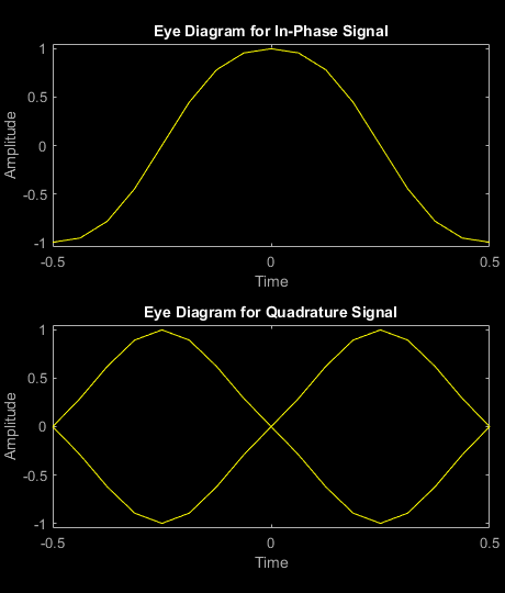
Generate random bit data and apply GFSK modulation. Use a scatter plot to view the constellation.

numSym = 100;
x = randi([0 1],numSym*gfskMod.SamplesPerSymbol,1);
y = gfskMod(x);
eyediagram(y,16)

Figure Eye Diagram contains 2 axes objects. Axes object 1 with title Eye Diagram for In-Phase Signal, xlabel Time, ylabel Amplitude contains an object of type line. This object represents In-phase. Axes object 2 with title Eye Diagram for Quadrature Signal, xlabel Time, ylabel Amplitude contains an object of type line. This object represents Quadrature.

Demodulate the GFSK-modulated data. To verify that the demodulated signal data is equal to the original data, account for the delay introduced by the Gaussian filtering in the GFSK modulation and demodulation processes.

z = gfskDemod(y);
delay = finddelay(x,z);
isequal(x(1:end-delay),z(delay+1:end))
ans = logical
   1

Plot the phase tree diagram for signals that have applied continuous phase modulation (CPM). A phase tree diagram superimposes many curves, each of which plots the phase of a modulated signal over time. The distinct curves result from different inputs to the modulator. This example defines settings for the CPM modulator, applies symbol mapping, and plots the results. Each curve represents a different instance of simulating the CPM modulator with a distinct (constant) input signal.

Define parameters for the example and create a CPM modulator System object™.

M = 2;                   % Modulation order
modindex = 2/3;          % Modulation index
sps = 8;                 % Samples per symbol
L = 5;                   % Symbols to display
pmat = zeros(L*sps,M^L); % Empty phase matrix 

cpm = comm.CPMModulator(M, ...
    ModulationIndex=modindex, ...
    FrequencyPulse="Raised Cosine", ...
    PulseLength=2, ...
    SamplesPerSymbol=sps);

Use a for-loop to apply the mapping of the input symbol to the CPM symbols, mapping 0 to -(M-1), 1 to -(M-2), and so on. Populate the columns of the phase matrix with the unwrapped phase angle of the modulated symbols.

for ip_sig = 0:(M^L)-1
    s = int2bit(ip_sig,L,1);
    s = 2*s + 1 - M;
    x = cpm(s);
    pmat(:,ip_sig+1) = unwrap(angle(x(:)));
end
pmat = pmat/(pi*modindex);
t = (0:L*sps-1)'/sps;

Plot the CPM phase tree.

plot(t,pmat);
title('CPM Phase Tree')
xlabel('Samples')
ylabel('Phase (radians)')

Figure contains an axes object. The axes object with title CPM Phase Tree, xlabel Samples, ylabel Phase (radians) contains 32 objects of type line.

More About

expand all

References

[1] Anderson, John B., Tor Aulin, and Carl-Erik Sundberg. Digital Phase Modulation. New York: Plenum Press, 1986.

Extended Capabilities

Version History

Introduced in R2012a

expand all