comm.MSKModulator
Modulate using MSK method
Description
The comm.MSKModulator
System object™ modulates using the minimum shift keying method. The output is a baseband
representation of the modulated signal. For more information, see Algorithms.
To modulate a signal using minimum shift keying:
Create the
comm.MSKModulatorobject and set its properties.Call the object with arguments, as if it were a function.
To learn more about how System objects work, see What Are System Objects?
Creation
Description
mskmodulator = comm.MSKModulator
mskmodulator = comm.MSKModulator(Name=Value)mskmodulator = comm.MSKModulator(InitialPhaseOffset=pi/2) specifies
an initial phase of pi/2 radians for the modulated waveform.
Properties
Usage
Syntax
Description
Input Arguments
Output Arguments
Object Functions
To use an object function, specify the
System object as the first input argument. For
example, to release system resources of a System object named obj, use
this syntax:
release(obj)
Examples
Create an MSK modulator, an AWGN channel, and an MSK demodulator. Use a phase offset of .
mskmodulator = comm.MSKModulator( ...
    BitInput=true, ...
    InitialPhaseOffset=pi/4);
awgn = comm.AWGNChannel( ...
    NoiseMethod='Signal to noise ratio (SNR)', ...
    SNR=0);
mskdemodulator = comm.MSKDemodulator( ...
    BitOutput=true, ...
    InitialPhaseOffset=pi/4);
Create an error rate calculator. Account for the delay caused by the Viterbi algorithm.
ber = comm.ErrorRate(ReceiveDelay=mskdemodulator.TracebackDepth);
Transmit 100 3-bit words.
    for counter = 1:100
      data = randi([0 1],300,1);
      modSignal = mskmodulator(data);
      noisySignal = awgn(modSignal);
      receivedData = mskdemodulator(noisySignal);
      errorStats = ber(data, receivedData);
    end
    fprintf('Error rate = %f\nNumber of errors = %d\n', ...
      errorStats(1), errorStats(2))
Error rate = 0.000000
Number of errors = 0
Map binary sequences of zeros and ones to the output of an MSK modulator. This mapping also applies for GMSK modulation.
Create an MSK modulator that accepts binary inputs and has a samples per symbol value of 1.
mskmodulator = comm.MSKModulator(BitInput=true, SamplesPerSymbol=1);
Create an input sequence of all zeros. Modulate the sequence.
x = zeros(5,1);
y = mskmodulator(x)
y = 5×1 complex

   1.0000 + 0.0000i
   0.0000 - 1.0000i
  -1.0000 - 0.0000i
  -0.0000 + 1.0000i
   1.0000 + 0.0000i
Determine the phase angle for each point. Use the unwrap function to show the trend.
theta = unwrap(angle(y))
theta = 5×1

         0
   -1.5708
   -3.1416
   -4.7124
   -6.2832
A sequence of zeros causes the phase to shift by between samples.
Reset the modulator. Modulate an input sequence of all ones.
reset(mskmodulator)
x = ones(5,1);
y = mskmodulator(x)
y = 5×1 complex

   1.0000 + 0.0000i
   0.0000 + 1.0000i
  -1.0000 + 0.0000i
  -0.0000 - 1.0000i
   1.0000 - 0.0000i
Determine the phase angle for each point. Use the unwrap function to show the trend.
theta = unwrap(angle(y))
theta = 5×1

         0
    1.5708
    3.1416
    4.7124
    6.2832
A sequence of ones causes the phase to shift by between samples.
Compare Gaussian minimum shift keying (GMSK) and minimum shift keying (MSK) modulation schemes by plotting the eye diagram for GMSK with different pulse lengths and for MSK.
Set the samples per symbol variable.
sps = 8;
Generate random binary data.
data = randi([0 1],1000,1);
Create GMSK and MSK modulators that accept binary inputs. Set the PulseLength property of the GMSK modulator to 1.
gmskMod = comm.GMSKModulator( ...
    BitInput=true, ...
    PulseLength=1, ...
    SamplesPerSymbol=sps);
mskMod = comm.MSKModulator( ...
    BitInput=true, ...
    SamplesPerSymbol=sps);
Modulate the data using the GMSK and MSK modulators.
modSigGMSK = gmskMod(data);
modSigMSK = mskMod(data);
Pass the modulated signals through an AWGN channel having an SNR of 30 dB.
rxSigGMSK = awgn(modSigGMSK,30);
rxSigMSK = awgn(modSigMSK,30);
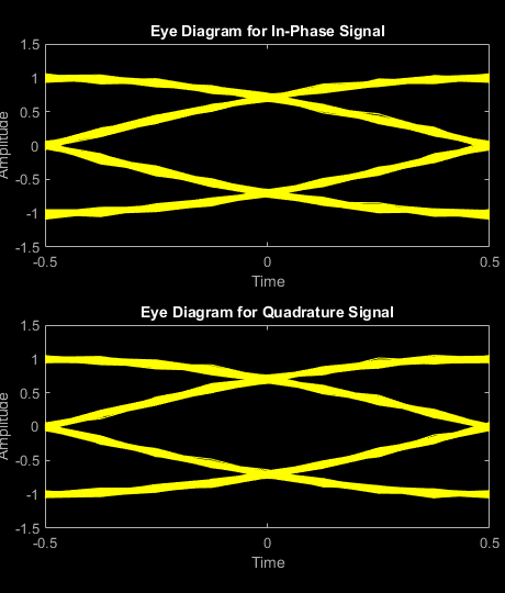
Use the eyediagram function to plot the eye diagrams of the noisy signals. With the GMSK pulse length set to 1, the eye diagrams are nearly identical.
eyediagram(rxSigGMSK,sps,1,sps/2)
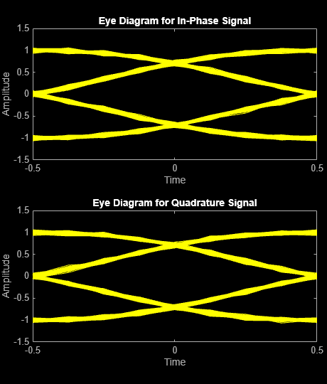
eyediagram(rxSigMSK,sps,1,sps/2)
Set the PulseLength property for the GMSK modulator object to 3. Because the property is nontunable, the object must be released first.
release(gmskMod)
gmskMod.PulseLength = 3;
Generate a modulated signal using the updated GMSK modulator object and pass it through the AWGN channel.
modSigGMSK = gmskMod(data);
rxSigGMSK = awgn(modSigGMSK,30);
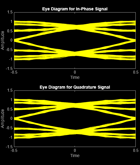
With continuous phase modulation (CPM) waveforms, such as GMSK, the waveform depends on values of the previous symbols as well as the present symbol. Plot the eye diagram of the GMSK signal to see that the increased pulse length results in an increase in the number of paths in the eye diagram.
eyediagram(rxSigGMSK,sps,1,sps/2)
Experiment by changing the PulseLength property of the GMSK modulator object to other values. If you set the property to an even number, you should set gmskMod.InitialPhaseOffset to pi/4 and update the offset argument of the eyediagram function from sps/2 to 0 for a better view of the modulated signal. In order to more clearly view the Gaussian pulse shape, you must use scopes that display the phase of the signal, as described in the View CPM Phase Tree Using Simulink example.
Algorithms
Differentially encoded minimum shift keying modulation uses pulse shaping to smooth the phase transitions of the modulated signal. The function q(t) is the phase response obtained from the frequency pulse, g(t), through this relation:.
The specified frequency pulse shape corresponds to this rectangular pulse shape expression for g(t).
| Pulse Shape | Expression |
|---|---|
Rectangular |
L is the main lobe pulse duration in symbol intervals.
The duration of the pulse, LT, is the pulse length in symbol intervals.
Extended Capabilities
Version History
Introduced in R2012aSee Also
Functions
Objects
comm.CPFSKModulator|comm.CPFSKDemodulator|comm.GMSKModulator|comm.GMSKDemodulator|comm.MSKDemodulator|comm.CPMModulator|comm.CPMDemodulator