comm.IQImbalanceCompensator
Compensate for IQ imbalance
Description
The comm.IQImbalanceCompensator
System object™ compensates for the imbalance between the in-phase and quadrature (IQ)
components of a modulated signal. The adaptive algorithm inherent to the IQ imbalance
compensator is compatible with M-PSK, M-QAM, and OFDM
modulation schemes, where M>2. For more information, see Algorithms.
Note
The output of the compensator might be scaled and rotated, that is, multiplied by a complex number, relative to the reference constellation. In practice, this transformation is not an issue because, before demodulation, receivers correct for it by using channel estimation.
To compensate for IQ imbalance:
Create the
comm.IQImbalanceCompensatorobject and set its properties.Call the object with arguments, as if it were a function.
To learn more about how System objects work, see What Are System Objects?
Creation
Description
iqcomp = comm.IQImbalanceCompensator
iqcomp = comm.IQImbalanceCompensator(Name=Value)comm.IQImbalanceCompensator(CoefficientSource="Input port") specifies
that the compensator coefficients must be provided when you call the object. For this
configuration, all other properties are disabled.
Properties
Usage
Syntax
Description
y = iqcomp(x,c)c, instead of generating
them internally. This syntax applies when the CoefficientSource property
is set to Input port. When using this syntax, adaptive estimation of
the compensator coefficient is disabled.
y = iqcomp(x,s)s. This syntax applies when the StepSizeSource property is set
to Input port.
y = iqcomp(x,a)a, to enable or disable
coefficient updates. This syntax applies when the AdaptInputPort property is set
to true.
y = iqcomp(x,s,a)s, and the adaptation control signal,
a, to enable and disable coefficient updates. This syntax applies
when the StepSizeSource property is set
to Input port and the AdaptInputPort property is set
to true.
[
also returns estimated compensation coefficients with input arguments from any of the
previous syntaxes. This syntax applies when the y,coef] = iqcomp(x,___)CoefficientOutputPort
property is set to Input port.
Input Arguments
Output Arguments
Object Functions
To use an object function, specify the
System object as the first input argument. For
example, to release system resources of a System object named obj, use
this syntax:
release(obj)
Examples
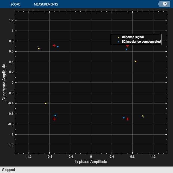
Mitigate the impacts of amplitude and phase imbalance on a QPSK modulated signal by using the comm.IQImbalanceCompensator System object™.
Generate random data symbols and apply QPSK modulation.
M = 4;                       % QPSK
spf = 1e6;                   % Samples per frame
data = randi([0 M-1],spf,1);
txSig = pskmod(data,M,pi/4);
Create a constellation diagram object to display the QPSK signal before and after IQ imbalance compensation. The reference constellation for the object does not require an update because the default QPSK reference constellation matches the transmitted signal.
cdscope = comm.ConstellationDiagram( ...
    NumInputPorts=2, ...
    ShowLegend=true, ...
    ChannelNames=["Impaired signal","IQ imbalance compensated"]);
Create an IQ imbalance compensator.
iqImbComp = comm.IQImbalanceCompensator;
Apply amplitude and phase imbalance to the transmitted signal.
ampImb = 5;                          % dB
phImb = 15;                          % deg
rxSig = iqimbal(txSig,ampImb,phImb);
On the receiver side, apply the IQ compensation algorithm to the impaired signal.
compSig = iqImbComp(rxSig);
To display the impaired signal and the IQ impairment compensated signal, load the last 1000 symbols of the signals into the constellation diagram object. The impaired signal constellation shows IQ amplitude and phase impairments. The impairment compensated signal constellation nearly aligns with the reference constellation.
cdscope(rxSig(spf - 1000:end),compSig(spf - 1000:end))
release(cdscope)
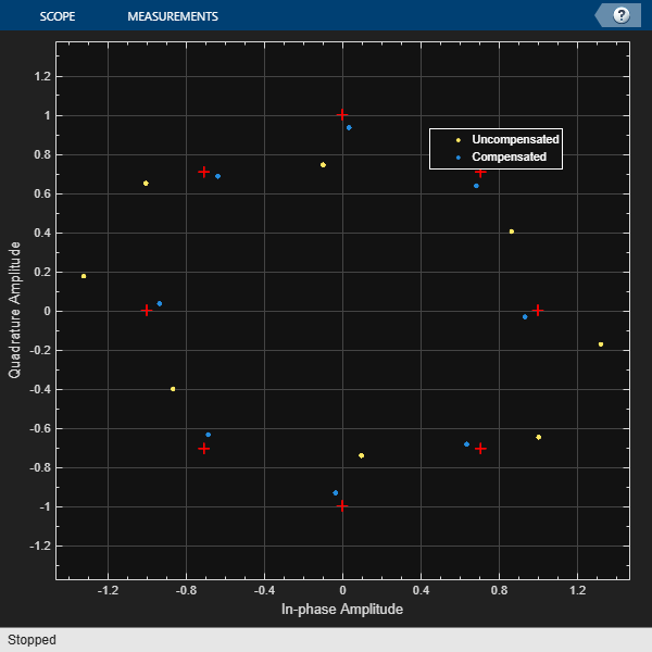
Compensate for an amplitude and phase imbalance on an 8-PSK signal by using the comm.IQImbalanceCompensator System object™ with external coefficients.
Generate an 8-PSK reference constellation. Create a constellation diagram System object. Configure the constellation diagram object to display only the last 100 data symbols of two input signals and provide the reference constellation.
refconst = pskmod(0:7,8,0);
cdscope = comm.ConstellationDiagram(...
    NumInputPorts=2, ...
    SymbolsToDisplaySource="Property", ...
    SymbolsToDisplay=100, ...
    ReferenceConstellation=refconst, ...
    ChannelNames=["Uncompensated","Compensated"]);
Create an I/Q imbalance compensator object with an input port for the algorithm coefficients.
iqcomp = comm.IQImbalanceCompensator( ...
    CoefficientSource="Input port");
Generate random data symbols and apply 8-PSK modulation.
data = randi([0 7],1000,1);
txSig = pskmod(data,8,0);
Apply amplitude and phase imbalance to the transmitted signal.
ampImb = 5;                          % dB
phImb = 15;                          % degrees
rxSig = iqimbal(txSig,ampImb,phImb);
Use the iqimbal2coef function to determine the compensation coefficient given the amplitude and phase imbalance.
compCoef = iqimbal2coef(ampImb,phImb);
Apply the compensation coefficient to the received signal when calling the iqcomp object. Display the resulting constellations for the uncompensated and compensated signal. You can see severe IQ imbalance in the uncompensated signal and the compensated signal constellation is nearly aligned with the reference constellation.
compSig = iqcomp(rxSig,compCoef);
cdscope(rxSig,compSig)
release(cdscope)
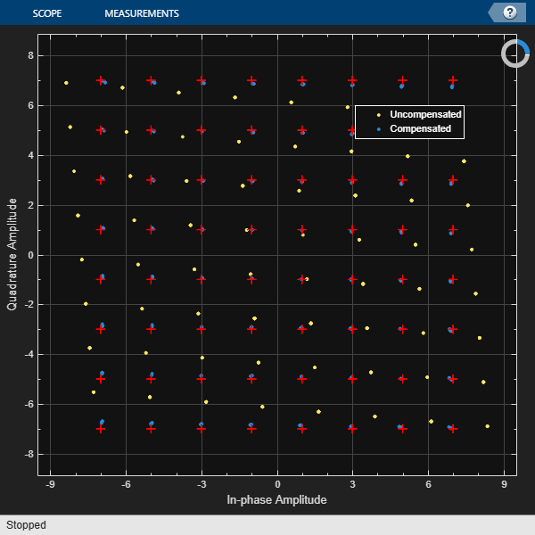
Remove an IQ imbalance from a 64-QAM signal and make the estimated coefficients externally available while setting the algorithm step size from an input port.
Create a constellation diagram object. Use name-value pairs to ensure that the constellation diagram displays only the last 256 data symbols, set the axes limits, and specify the reference constellation.
M = 64;
refC = qammod(0:M-1,M);
cdscope = comm.ConstellationDiagram(...
    NumInputPorts=2, ...
    SymbolsToDisplaySource="Property", ...
    SymbolsToDisplay=256, ...
    XLimits=[-10 10], ...
    YLimits=[-10 10], ...
    ReferenceConstellation=refC, ...
    ChannelNames=["Uncompensated","Compensated"]);
Create an IQ imbalance compensator System object™ in which the step size is specified as an input argument and the estimated coefficients are made available through an output port.
iqImbComp = comm.IQImbalanceCompensator( ...
    StepSizeSource="Input port", ...
    CoefficientOutputPort=true);
Generate random data symbols and apply 64-QAM modulation.
nSym = 30000;
data = randi([0 M-1],nSym,1);
txSig = qammod(data,M);
Apply amplitude and phase imbalance to the transmitted signal.
ampImb = 2;                          % dB
phImb = 10;                          % deg
rxSig = iqimbal(txSig,ampImb,phImb);
Specify the step size parameter for the IQ imbalance compensator.
stepSize = 1e-5;
Compensate for the IQ imbalance while setting the step size with an input argument. Plot the constellation diagram of the received signal. You can see that the compensated signal constellation is now nearly aligned with the reference constellation.
[compSig,estCoef] = iqImbComp(rxSig,stepSize);
cdscope(rxSig,compSig)
release(cdscope)
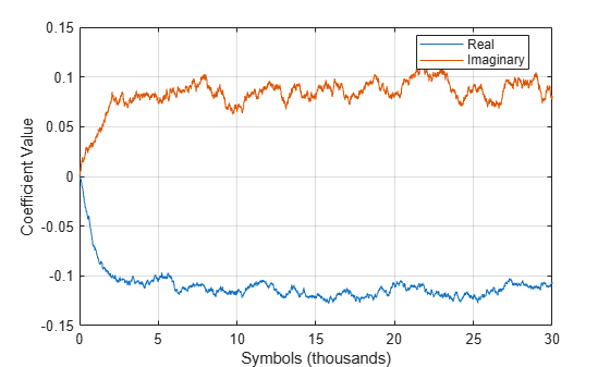
Plot the real and imaginary values of the estimated coefficients. The output coefficients show the simulation reaches a steady-state solution after approximately 5000 symbols.
plot((1:nSym)'/1000,[real(estCoef),imag(estCoef)])
grid
xlabel('Symbols (thousands)')
ylabel('Coefficient Value')
legend('Real','Imaginary','location','best')
Control the adaptation algorithm of the IQ imbalance compensator using an external argument.
Apply QPSK modulation to random data symbols.
data = randi([0 3],600,1);
txSig = pskmod(data,4,pi/4,'gray');
Create an IQ imbalance compensator in which the adaptation algorithm is controlled through an input port, the step size is specified through the StepSize property, and the estimated coefficients are made available through an output port.
iqImbComp = comm.IQImbalanceCompensator( ...
    AdaptInputPort=true, ...
    StepSize=0.001, ...
    CoefficientOutputPort=true);
Apply amplitude and phase imbalance to the transmitted signal.
ampImb = 5; % dB
phImb = 15; % deg
gainI = 10.^(0.5*ampImb/20);
gainQ = 10.^(-0.5*ampImb/20);
imbI = real(txSig)*gainI*exp(-0.5i*phImb*pi/180);
imbQ = imag(txSig)*gainQ*exp(1i*(pi/2 + 0.5*phImb*pi/180));
rxSig = imbI + imbQ;
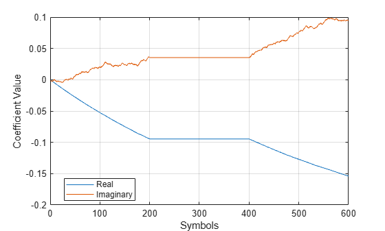
Break the compensation operation into three segments in which the compensator is enabled for the first 200 symbols, disabled for the next 200 symbols, and enabled for the last 200 symbols. Save the coefficient data in three vectors.
[~,estCoef1] = iqImbComp(rxSig(1:200),true);
[~,estCoef2] = iqImbComp(rxSig(201:400),false);
[~,estCoef3] = iqImbComp(rxSig(401:600),true);
Concatenate the complex algorithm coefficients and plot their real and imaginary parts. Observe that the coefficients do not adapt when the compensator is disabled.
estCoef = [estCoef1; estCoef2; estCoef3];
plot((1:600)',[real(estCoef) imag(estCoef)])
grid
xlabel('Symbols')
ylabel('Coefficient Value')
legend('Real','Imaginary','location','best')
Algorithms
Imbalance between the in-phase and quadrature components of signal output from RF receivers can be cost-effectively compensated rather than improving the analog front-end RF hardware. Direct conversion receivers, in particular, introduce IQ imbalance. A circularity-based blind compensation algorithm is used as the basis for the IQ imbalance compensator.
A generalized IQ imbalance model is shown, where g is the amplitude imbalance and ϕ is the phase imbalance. For no impairment, g = 1 and ϕ = 0. In the figure, H(f) is the nominal frequency response of the branches due to, for example, low-pass filters. HI(f) and HQ(f) represent the portions of the in-phase and quadrature amplitude and phase responses that differ from the nominal response. With perfect matching, HI(f) = HQ(f) = 1.
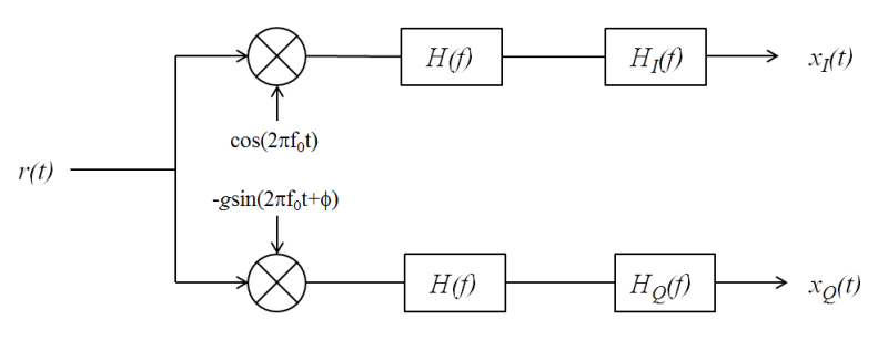
Let z(t) be the ideal baseband equivalent signal of the received signal, r(t), where its Fourier transform is denoted as Z(f). Given the generalized IQ imbalance model, the Fourier transform of the imbalanced signal, x(t) = xI(t) + xQ(t), is
where G1(f) and G2(f) are the direct and conjugate components of the IQ imbalance. These components are defined as
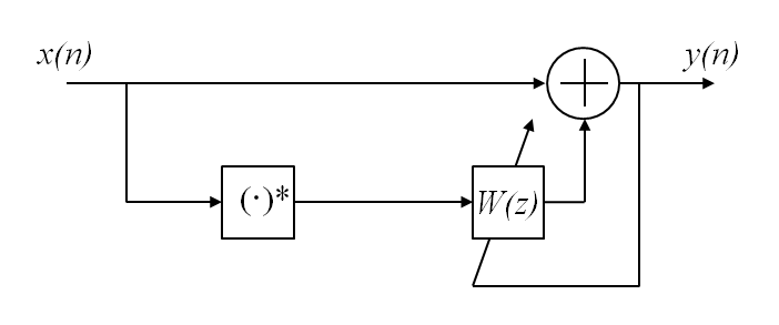
Applying the inverse Fourier transform to X(f), the signal model becomes x(t) = g1(t) × z(t) + g2(t) × z*(t).
This transformation suggests the compensator structure as shown in which discrete-time notation expresses the variables. The compensated signal is expressed as y(n) = x(n) + wx*(n).
An algorithm of the form
is used to determine the weights because it ensures that the output is
proper, that is, the condition, E[y2(n)]
= 0 is satisfied. For further details, see [1]. The initial value
of w is determined by the initial compensator coefficient, which has a
default value of 0 + 0i. M is the adaptation step size
as described in StepSize.
References
[1] Anttila, L., M. Valkama, and M. Renfors. "Blind compensation of frequency-selective I/Q imbalances in quadrature radio receivers: Circularity-based approach.", Proc. IEEE® ICASSP (2007): III-245–48.
[2] Kiayani, A., L. Anttila, Y. Zou, and M. Valkama, "Advanced Receiver Design for Mitigating Multiple RF Impairments in OFDM Systems: Algorithms and RF Measurements." Journal of Electrical and Computer Engineering 2012.
Extended Capabilities
Version History
Introduced in R2014b