Acquire Optimized Fault Analysis Data with Analog Triggering
R2026bThis example shows how to configure an analog input channel as an analog trigger to efficiently acquire vibration data using an accelerometer. In industrial settings, monitoring machinery vibrations is crucial for detecting anomalies and predicting maintenance needs.
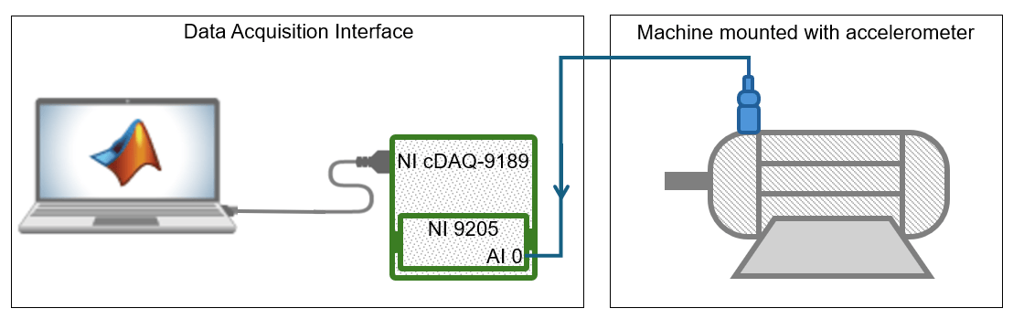
This example uses a single-axis accelerometer to measure vibrations from the machine under test and an NI™ 9205 module in the CompactDAQ Chassis NI cDAQ-9189 for data acquisition. Connect the NI module to the accelerometer. The NI module uses an analog input channel to read voltage from the accelerometer and triggers data acquisition when vibrations exceed 2 . On triggering, the NI module acquires 1000 samples of data at a high sampling rate of 10 kHz, enabling detailed analysis, such as FFT-based diagnostics. This setup reduces unnecessary data logging and processing overheads, enabling real-time fault detection and supporting predictive maintenance.
Calculate Bias Voltage and Trigger level
To calculate the bias voltage of the accelerometer, measure its output voltage when the machine under test is powered off. This example uses an accelerometer with a bias voltage of 2.5 . Store the bias voltage in vBias.
vBias = 2.5;
Determine the output voltage of the accelerometer for 2 vibration using this formula.
This example uses an accelerometer with a sensitivity of 40 . For an accelerometer with 2.5 bias voltage and 40 sensitivity, the output voltage is 2.58 when it detects 2 vibration. Store this output voltage value as the trigger level for data acquisition.
triggerLevel = 2.58; % Voltage detected at 2g vibration thresholdCreate DataAcquisition Object and Configure Properties
Create a DataAcquisition object using the daq function and set the device scan rate as 10 kHz using the Rate property. Add an analog input channel of measurement type Voltage using the addinput function.
dq = daq("ni");
dq.Rate = 10000;
ch = addinput(dq, "cDAQ1Mod1", "ai0", "Voltage");
Configure Channel for Analog Edge Triggering
Configure the device channel with the calldaqlib function, specifying the NI DAQmx function, trigger source, trigger slope, and trigger level.
calldaqlib(dq, "DAQmxCfgAnlgEdgeStartTrig", "cDAQ1Mod1/ai0", "DAQmx_Val_RisingSlope", triggerLevel);
dq.ScansAvailableFcn = @(src, event) disp("Trigger detected! Acquiring data...");
Acquire Machine Vibration Data
Acquire 1000 samples of data over a duration of 100 ms when the device detects a trigger. Perform data acquisition in the background using the start and read functions.
acqDuration = 1000 / dq.Rate;
start(dq, "Duration", seconds(acqDuration));
disp("Monitoring vibration... Waiting for trigger (vibration > 2g)...");
Monitoring vibration... Waiting for trigger (vibration > 2g)...
pause(5);
data = read(dq, "all");
Display Data
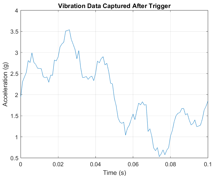
Convert the acquired vibration data from voltage to values. Plot and examine the converted vibration data. You can use this data for machine analysis and to develop predictive maintenance strategies.
if isempty(data)
    disp("No trigger detected.")
else
    % Plot the vibration data
    figure;
    plot(data.Time, (data.cDAQ1Mod1_ai0-vBias).*25);
    xlabel("Time (s)");
    ylabel("Acceleration (g)");
    title("Vibration Data Captured After Trigger");
    grid on;
end