Intersection Collision Warning Using V2X Communication
This example shows how to design a vehicle-to-everything (V2X) communication-based intersection collision warning system to prevent collisions among vehicles at road intersections, using Simulink®, and simulate it with RoadRunner Scenario.
Introduction
RoadRunner Scenario is an interactive editor that enables you to design scenarios for simulating and testing automated driving systems. You can place vehicles, define their paths and interactions in the scenario, and then simulate the scenario in the editor. RoadRunner Scenario supports in-editor playback for scenario visualization and connecting to other simulators, such as MATLAB® and Simulink, for cosimulation.
This example shows how to generate V2X messages, such as basic safety messages (BSM), signal phase and timing (SPAT) messages, and map (MAP) messages. It then shows how to utilize these messages in an intersection collision warning system and a traffic signal follower system to warn about potential collisions at road intersections and ensure vehicles adhere to traffic signals to prevent accidents.
In this example, you:
Set Up Environment — Configure MATLAB to interact with RoadRunner Scenario.
Explore Scene and Scenario — Explore the RoadRunner scene and scenario that defines actions for the ego vehicle and other actors.
Explore Test Bench Model — Explore the Simulink model, which includes the RoadRunner interfaces, transmitter and receiver for V2X communication, traffic signal follower, intersection collision warning algorithm, and visualization components.
Model V2X Communication — Generate BSM, SPAT, and MAP messages to model V2X communication.
Model ICW Algorithm — Analyze collision risk at intersections based on BSM and MAP messages, and generate collision warnings.
Model Traffic Signal Follower — Use SPAT and MAP messages to obtain traffic signal data for the ego vehicle and apply decision logic to control its speed.
Simulate Test Bench Model — Simulate the model and evaluate the results of the intersection collision warning algorithm.
Explore Other Scenarios — Test the system in other scenarios under additional conditions.
Set Up Environment
Set up the RoadRunner environment to cosimulate with RoadRunner Scenario.
Start the RoadRunner application interactively by using the roadrunnerSetup function. When the function opens a dialog box, specify the RoadRunner Project Folder and RoadRunner Installation Folder locations.
rrApp = roadrunnerSetup;
The rrApp RoadRunner object enables you to interact with RoadRunner from the MATLAB workspace. You can open the scenario and update scenario variables using this object. For more information on this object, see roadrunner.
This example uses these files, which you must add to the RoadRunner project.
USCityBlockBidirectional.rrscene— Scene file that describes a large city with bidirectional roads and several junctions.scenario_01_ICW_Ego_MoveStraight.rrscenario— RoadRunner scenario file that describes the actors and their trajectories within theUSCityBlockBidirectionalscene. The scenario contains an ego vehicle and three target vehicles, all approaching a junction. At the junction, the ego vehicle proceeds straight, adhering to traffic signals while assessing collision risks. Among the target vehicles, two comply with the traffic signals, while one disregards them and is on a collision course with the ego vehicle.scenario_02_ICW_Ego_TurnLeft.rrscenario— RoadRunner scenario file that describes the actors and their trajectories in theUSCityBlockBidirectionalscene. The scenario contains an ego vehicle and four target vehicles, three of which are approaching the junction. The ego vehicle makes a left turn at the junction and, while crossing, adheres to traffic signals and evaluates collision risks. Among the target vehicles, one disregards the traffic signals and is on a collision course with the ego vehicle.ICWBehaviour.rrbehavior.rrmeta— Behavior file that associates the behavior of the intersection collision warning model, implemented using Simulink, to the ego vehicle in the RoadRunner scenario.
Copy the files to the RoadRunner project.
rrProjectPath = rrApp.status.Project.Filename;
openProject("IntersectionCollisionWarning");
icwExampleProject = currentProject;
projectPath = convertStringsToChars(icwExampleProject.RootFolder);
projectRootFolder = projectPath(1:find(projectPath=='\',1,'last')-1);
copyfile(fullfile(projectRootFolder,"IntersectionCollisionWarning/TestBench/scenario_01_ICW_Ego_MoveStraight.rrscenario"),fullfile(rrProjectPath,"Scenarios"),"f");
copyfile(fullfile(projectRootFolder,"IntersectionCollisionWarning/TestBench/scenario_02_ICW_Ego_TurnLeft.rrscenario"),fullfile(rrProjectPath,"Scenarios"),"f");
copyfile(fullfile(projectRootFolder,"IntersectionCollisionWarning/TestBench/ICW.rrbehavior.rrmeta"),fullfile(rrProjectPath,"Assets","Behaviors"),"f");
This example uses additional supporting files and MAT files that are not part of the project folder. Add these files to the project path.
addpath(fullfile(icwExampleProject.RootFolder,"../"));
Explore Scene and Scenario
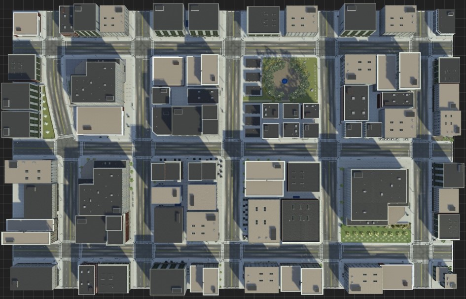
This example uses the USCityBlockBidirectional scene. This scene is a 3D representation of a compact city block with 15 intersections. All roads in the scene are two-way roads with four lanes.
Open the scene.
openScene(rrApp,"USCityBlockBidirectional.rrscene")
To connect to the RoadRunner Scenario server for cosimulation, first open a new empty scenario using the newScenario function, and then connect to the RoadRunner Scenario server using the createSimulation function. Once connected, enable data logging.
newScenario(rrApp);
rrSim = createSimulation(rrApp);
set(rrSim,Logging="on")
rrSim is a ScenarioSimulation object. Use this object to set variables and to read scenario-related information. Set the simulation to run at a step size of 0.1.
Ts = 0.1;
set(rrSim,StepSize=Ts)
Open the scenario.
openScenario(rrApp,"scenario_01_ICW_Ego_MoveStraight.rrscenario")
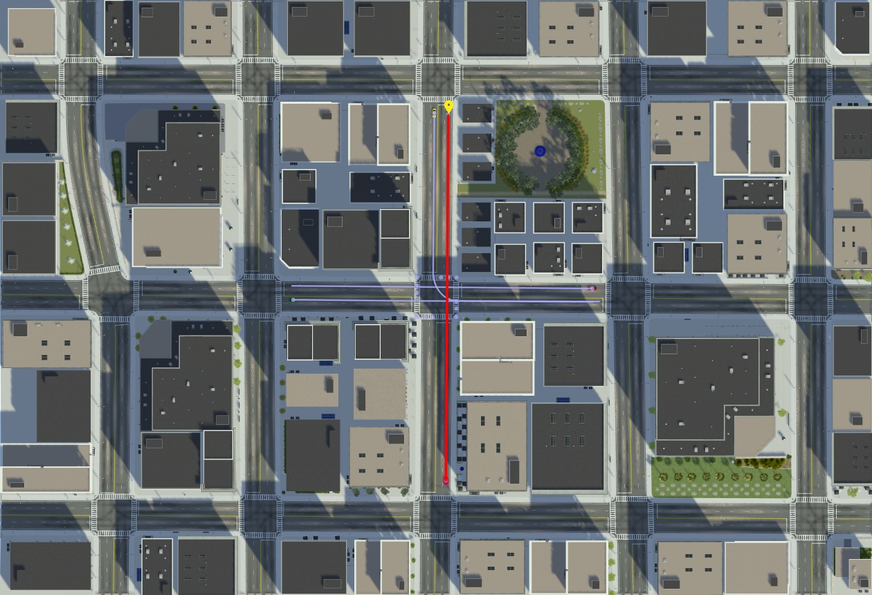
This scenario contains a blue ego vehicle and three target vehicles, all approaching a junction. The green and yellow target vehicles comply with the traffic signals, while the red target vehicle ignores the red signal and proceeds through the junction. As the ego vehicle approaches the junction, it stops at the stop line because the signal for the straight maneuver road is still red. The ego vehicle waits until the signal turns green. Once the signal turns green, the ego vehicle begins to cross the junction, but encounters the red target vehicle, which is crossing the junction while disregarding the red signal. The intersection collision warning (ICW) algorithm detects a potential collision and decelerates the ego vehicle to avoid a collision with the red target vehicle. After the red target vehicle has passed, the ego vehicle continues on its path.
Explore Test Bench Model
In this example, you use a system-level simulation test bench model to simulate and test the behavior of the intersection collision warning system with RoadRunner Scenario.
Open the test bench model.
open_system("ICWTestBench")
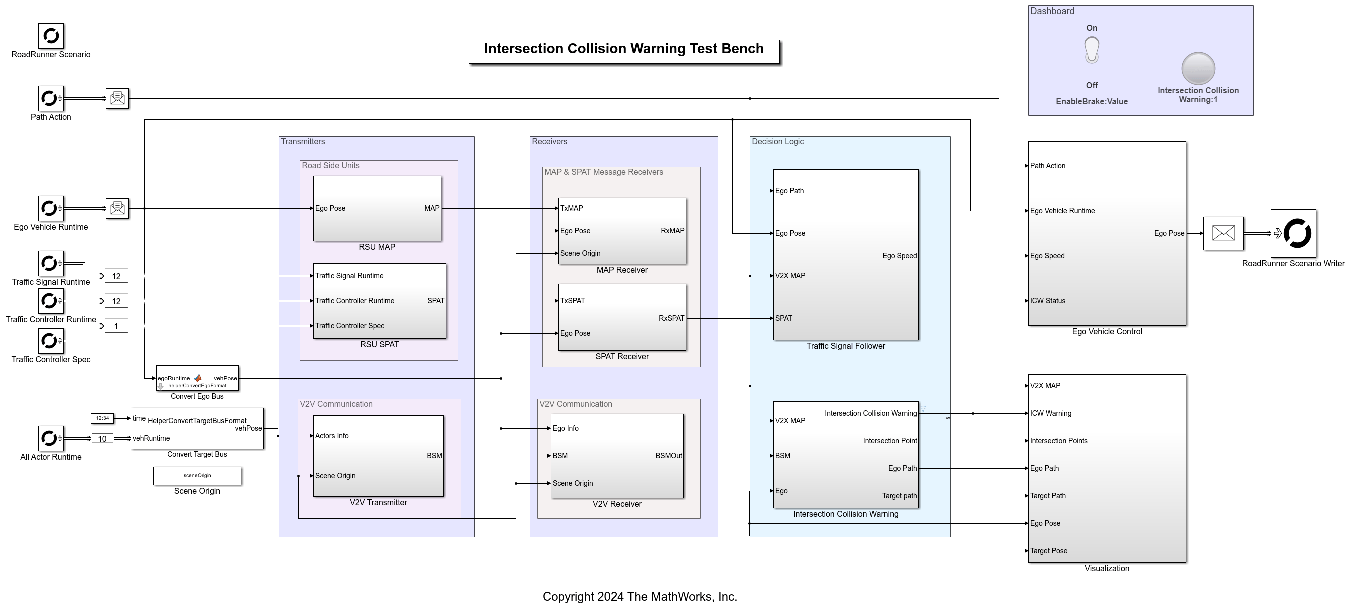
The test bench model contains RoadRunner Scenario blocks, which configure, read from, and write to RoadRunner Scenario. It also contains these modules:
V2X Transmitter Modules
RSU MAP— Subsystem that models a roadside unit, which transmits V2X MAP messages for the region in which the ego vehicle is present.RSU SPAT— Subsystem that models a roadside unit, which transmits V2X SPAT messages to convey traffic signal status and timing information to vehicles in the vicinity of the RSU.V2V Transmitter— Subsystem that models a vehicle-to-vehicle transmitter, which sends BSM messages to nearby vehicles to share information such as position, speed, and heading to enhance situational awareness and safety.
V2X Receiver Modules
MAP Receiver— Subsystem that models the message receiver of an ego vehicle, which receives V2X MAP messages sent by the roadside units based on the precomputed channel characteristics.SPAT Receiver— Subsystem that models the message receiver of an ego vehicle, which receives V2X SPAT messages sent by the roadside units based on the precomputed channel characteristics.V2V Receiver— Subsystem that receives V2V messages from other vehicles, based on the precomputed channel characteristics.
Algorithm and Visualization Modules
Traffic Signal Follower— Subsystem that uses MAP and SPAT messages to control the vehicle's speed based on traffic signal status.Intersection Collision Warning— Subsystem that models the intersection collision warning algorithm that analyzes V2V and MAP data to predict potential collisions at the intersections and provides warnings.Ego Vehicle Control— This subsystem enables the ego vehicle to follow the path specified in the RoadRunner Scenario. It takes the ego pose and the path as input and writes back the updated ego pose to RoadRunner Scenario. The block also controls ego vehicle speed based on collision warning and traffic signal status.Visualization— A graphical interface that displays the map data, vehicle position, traffic signal status, and intersection collision warning analysis.
RoadRunner Scenario Blocks
The RoadRunner Scenario blocks consist of:
RoadRunner Scenario— Defines the interface for an actor model.Path Action— RoadRunner Scenario Reader block that reads the path of the ego vehicle.Ego Vehicle Runtime— RoadRunner Scenario Reader block that reads ego vehicle runtime information.Traffic Signal Runtime— RoadRunner Scenario Reader block that reads the runtime information of all traffic signals.Traffic Signal Controller Runtime— RoadRunner Scenario Reader block that reads the runtime information of all traffic signal controllers.Traffic Signal Controller Spec— RoadRunner Scenario Reader block that reads the static attributes associated with all the traffic signal controllers.All Actor Runtime— RoadRunner Scenario Reader block that reads the poses of target actors.Ego Vehicle Runtime— RoadRunner Scenario Writer block that writes the ego vehicle runtime information to RoadRunner Scenario.
Model V2X Communication
For intersection collision warning applications, V2X communication plays a crucial role in enhancing situational awareness through real-time data exchange between vehicles and infrastructure. This example shows how to generate and simulate V2X messages, such as BSM, SPAT, and MAP messages. The Transmitter and the Receiver modules represent the V2X message communications in the testbench model.
Model Vehicle-to-Vehicle (V2V) Communication
V2V communication enables vehicles to share vital information, such as speed, position, and direction, that helps in the prediction and prevention of potential collisions, even with non-line-of-sight obstacles.
In this example, the V2V Transmitter and the V2V Receiver subsystems model the vehicle-to-vehicle (V2V) communication. The V2V Transmitter block contains the HelperV2VTransmitter System object™, which implements the transmitters of all the vehicles in a given scenario and generates the BSMs for them. On the receiving end, the V2V Receiver subsystem, utilizing the HelperV2VReceiver object, processes incoming BSMs, ego vehicle data, and scene origin information. The system uses precomputed channel characteristics to determine message reception, based on the throughput percentage relative to the distance between transmitter and receiver.
For more information about V2V communication and BSMs, see the Intersection Movement Assist Using Vehicle-to-Vehicle Communication example.
Model Vehicle-to-Infrastructure (V2I) Communication
V2I communication enables road and traffic signal infrastructure to share map and signal information with the vehicles, which assists in better maneuvering at the junction.
The RSU SPAT and SPAT Receiver subsystems simulate V2I communication between vehicles and traffic signal infrastructure. The RSU SPAT subsystem gathers traffic signal data from RoadRunner Reader blocks and generates SPAT messages indicating the traffic signal status for the intersections in the scene. The SPAT Receiver subsystem, utilizing the HelperSPATReceiver System object, models the receiver behavior of the ego vehicle. It uses precomputed channel characteristics to determine if the SPAT message has been received. If the throughput for a given distance between transmitter and receiver exceeds a preset threshold, the ego successfully receives the message.
The RSU MAP and MAP Receiver subsystems model the V2I communications between the vehicles and the road infrastructure. The RSU MAP subsystem, using the HelperRoadSideUnit System object, models the RSU that transmits the map information of its region. This subsystem receives the position of the ego vehicle position input, takes the MAP message of the entire scene as a mask parameter, and outputs the MAP message for the ego region. It generates the output MAP message based on the ego vehicle's position by selecting a specific area from the MAP message of the entire scene. This effectively simulates a real RSU broadcasting V2X MAP messages for its region. The System object converts the output MAP message structure into a serialized format using the jsonencode function, which returns a character vector. Then, the System object converts the character vector to a numeric double representation. This enables faster simulation. The MAP Receiver subsystem, utilizing the HelperMAPReceiver System object, models the receiver behavior of the ego vehicle and also uses the precomputed channel characteristics to receive the message.
Model Intersection Collision Warning Algorithm
The Intersection Collision Warning subsystem in the testbench model assesses the collision risk for the ego vehicle using the ego pose, BSM messages, and MAP messages, and generates the ICW warning.
Open the Intersection Collision Warning subsystem.
open_system("ICWTestBench/Intersection Collision Warning")
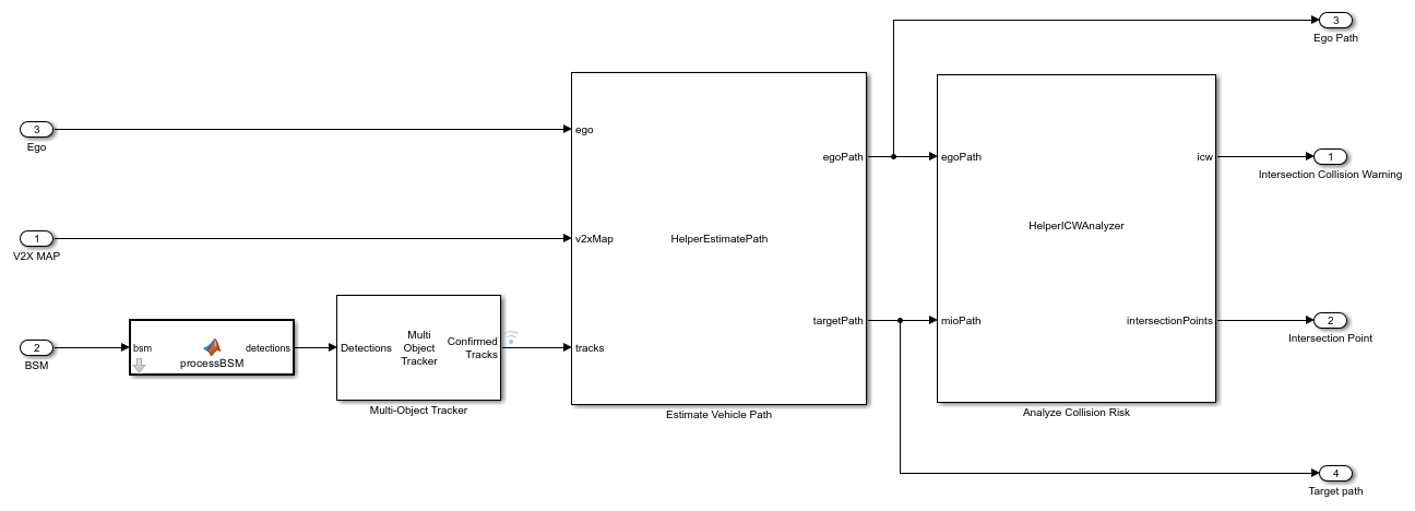
The Intersection Collision Warning subsystem takes the ego pose, BSM messages, and MAP messages as inputs. The processBSM MATLAB function converts the BSM messages to object detections. The multi-object tracker takes the detections as input and outputs the tracks for each vehicle to reduce the noise from the BSM messages. The HelperEstimatePath MATLAB System object takes in the ego pose, MAP messages, and the detected tracks to predict the path of each vehicle. For path prediction and collision risk analysis, the model considers only the vehicles approaching the junction, identified using the MAP message. The predicted path of the vehicle depends on its yaw rate. When the yaw rate is close to zero, the path is a straight line. However, when the yaw rate is higher, the path is circular. In the case of a circular path, the yaw rate and the speed of the vehicle determines the radius of curvature of the path [1]. The HelperICWAnalyzer System object takes the predicted paths of the ego and the target vehicles as inputs to find possible intersection points and generate the ICW warning. Based on the time to the intersection point of the ego vehicle, the time gap between the ego and target vehicles, the ICW system issues warnings at three levels: low, moderate, and high.
Low— Time to the intersection point of the ego vehicle is greater than or equal to 3 seconds, regardless of the time gap.Moderate— Time to the intersection point of the ego vehicle is less than 3 seconds, but there is a sufficient time gap of 2.5 seconds or more between the ego and target vehicles.High— Time to the intersection point of the ego vehicle is below 3 seconds, the time gap is also less than 2.5 seconds, and the estimated time to reach the stop line is less than 10 seconds. If the estimated time to the stop line is 10 seconds or more, the system defaults to a moderate warning instead of a high warning.
Model Traffic Signal Follower
The Traffic Signal Follower subsystem in the testbench model uses traffic signal data from the SPAT message, along with the position of the ego vehicle and the MAP message. It uses this information to implement decision logic that regulates the speed of the ego vehicle to obey the traffic signals.
Open the Traffic Signal Follower subsystem.
open_system("ICWTestBench/Traffic Signal Follower")
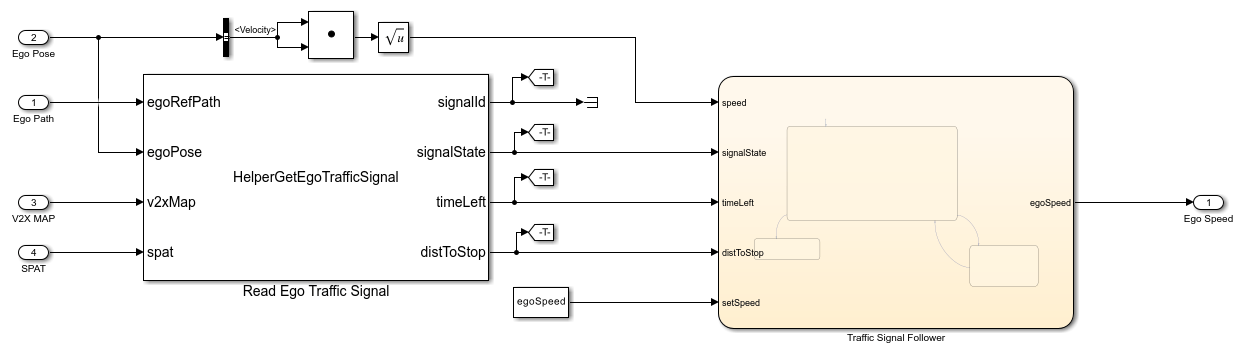
The HelperGetEgoTrafficSignal System object identifies the lane on which the ego vehicle is located based on the position of the ego vehicle and MAP message. It identifies the corresponding signal for the ego vehicle lane and signal status from the MAP and SPAT messages, respectively. The block outputs the current state of this signal, the time left for the current signal state and the distance to the stop line. The Stateflow® chart then uses this information to decide whether the ego vehicle brakes or continues moving. If the current state is red or yellow, and the time left is greater than the arrival time of the ego vehicle at the junction, the Stateflow model reduces the speed of the ego vehicle. Otherwise, the ego vehicle continues at the set speed.
Simulate Test Bench Model
This example uses the helperSLICWSetup helper function to set up the scenario and initialize model parameters. Configure the model to use the scenario_01_ICW_Ego_MoveStraight scenario.
helperSLICWSetup(rrApp,rrSim,scenarioFileName="scenario_01_ICW_Ego_MoveStraight")
Simulate the scenario, and observe the interaction of the ego vehicle with traffic signals. Additionally, observe how the intersection collision warning system triggers to detect potential collisions and issues warnings to prevent collisions between the ego and target vehicles.
set(rrSim,SimulationCommand="Start")
while strcmp(get(rrSim,"SimulationStatus"),"Running")
   pause(1)
end
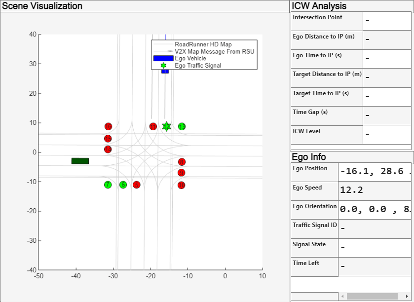
The Visualization subsystem generates a MATLAB figure that displays this information:
Scene Visualization — Displays the map data, positions, and predicted paths of each incoming vehicle and path intersection point, as well as the traffic signal status. The ego-associated traffic signal is marked with a hexagonal marker, while the other signals are marked with circular markers.
ICW Analysis — Displays the intersection point, distance, and time to intersection point between the ego and the target vehicle, and the ICW warning level.
Ego Info — Displays the position, orientation, and speed of ego vehicle. It also shows the ID and status of the traffic signal associated with the ego vehicle.
During the simulation, the ego vehicle follows the specified path at a set speed of 15 m/s. When the ego vehicle approaches the junction and the signal is red, the traffic signal follower reduces the speed of the ego vehicle, bringing it to a stop near the stop line. After the signal turns green, the traffic signal follower increases the speed of the ego vehicle, enabling it to cross the junction and continue following the specified straight path. However, as the ego vehicle is crossing the junction, a red target vehicle ignores the red signal and enters the intersection. In response, the intersection collision warning algorithm of the ego vehicle triggers a high-level warning, prompting the ego vehicle control block to reduce the speed of the ego vehicle to avoid a collision. After the target vehicle has safely crossed, the ego vehicle resumes and cross the junction safely.
Explore Other Scenarios
The example provides an additional scenario that is compatible with the ICWTestBench model. You can configure the Simulink model and workspace to simulate this scenario by using the helperSLICWSetup function:
helperSLICWSetup(rrApp,rrSim,scenarioFileName="scenario_02_ICW_Ego_TurnLeft")
References
[1] SAE International. Road Safety Applications. J2945/4_202305. SAE International, issued May 10, 2023. https://www.sae.org/standards/content/j2945/4_202305/.
[2] Park Seo-Wook, Raynier Suresh, and Anusha Ailuri. "Collision Avoidance System at Urban Intersections Using V2X Communication." SAE International, 2025. https://saemobilus.sae.org/papers/collision-avoidance-system-urban-intersections-using-v2x-communication-2025-01-8030.
See Also
Blocks
Objects
Functions
roadrunnerSetup|openScene|openScenario|open_system(Simulink)