Configure Simulink Environment for Signal Processing Models
About DSP Simulink Model Templates
DSP Simulink® model templates let you automatically configure Simulink environment with recommended settings for digital signal processing modeling. DSP Simulink model templates let you reuse settings, including configuration parameters. You can create models from templates that use best practices and take advantage of previous solutions to common problems. Instead of the default canvas of a new model, select a template model to help you get started.
For more information on Simulink model templates, see Create Template from Model (Simulink).
Create Model Using DSP System Toolbox Simulink Model Template
To create a new blank model and open the library browser:
On the MATLAB® Home tab, in the File section, click New > Simulink Model. The Simulink Start Page opens with built-in Simulink model templates.
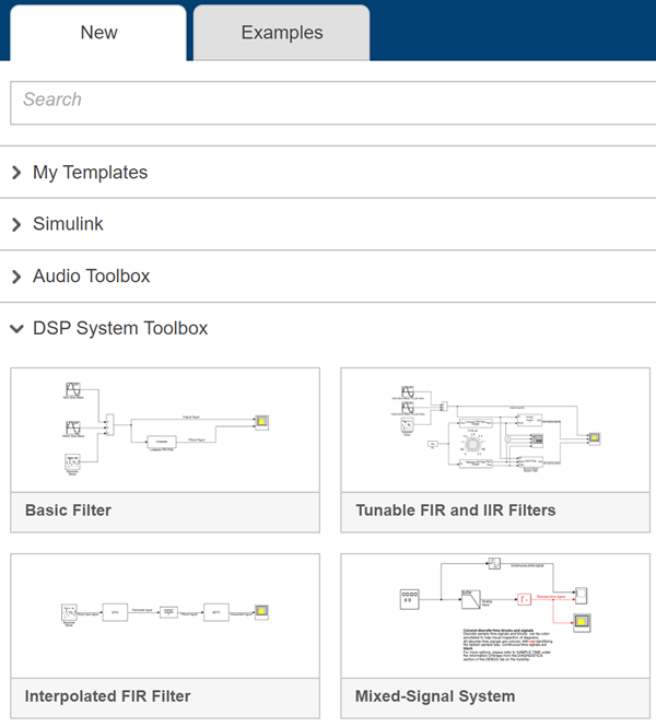
Click one of the templates under DSP System Toolbox to create a model with settings suitable for use with DSP System Toolbox™. A new model using the template settings and contents appears in the Simulink Editor. The model is only in memory until you save it.
To access the library browser, click Library Browser on the model toolstrip.
DSP Simulink Model Templates
When you create a model by choosing one of the DSP Simulink model templates, the model is configured to use the settings recommended for DSP System Toolbox. This table shows some of these settings.
| Configuration Parameter | Setting |
|---|---|
| SingleTaskRateTransMsg | error |
| multiTaskRateTransMsg | error |
| Solver | fixedstepdiscrete |
| EnableMultiTasking | Off |
| StartTime | 0.0 |
| StopTime | inf |
| FixedStep | auto |
| SaveTime | off |
| SaveOutput | off |
| AlgebraicLoopMsg | error |
| SignalLogging | off |
| FrameProcessingCompatibilityMsg | error |
These are the Simulink model templates in DSP System Toolbox:
Basic Filter
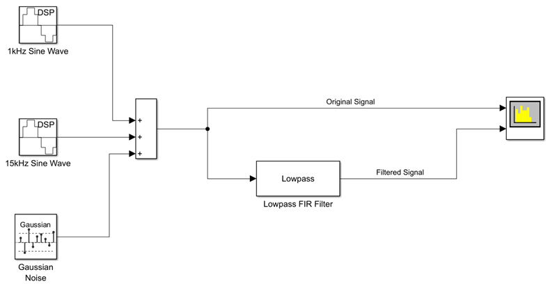
Click on Basic Filter to create a basic filtering model configured with settings recommended for DSP System Toolbox.
This model implements a lowpass filter and enables you to compare the filtered signal with the original signal. The model acts as a starting point for modeling filtering algorithms in Simulink using DSP System Toolbox.
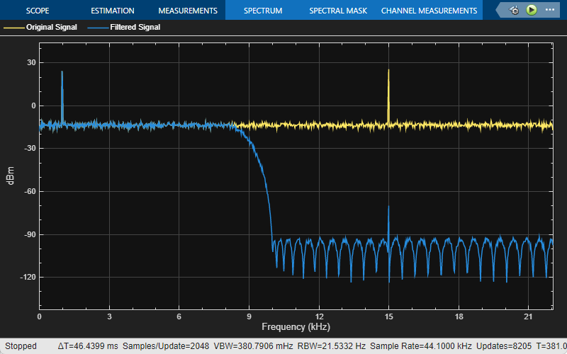
Here is the Spectrum Analyzer output showing the original signal and the filtered signal. The input signal contains tones at 1 kHz and 15 kHz. The 1 kHz tone gets passed in the filtered output while the 15 kHz tone gets attenuated.
Tunable FIR and IIR Filters
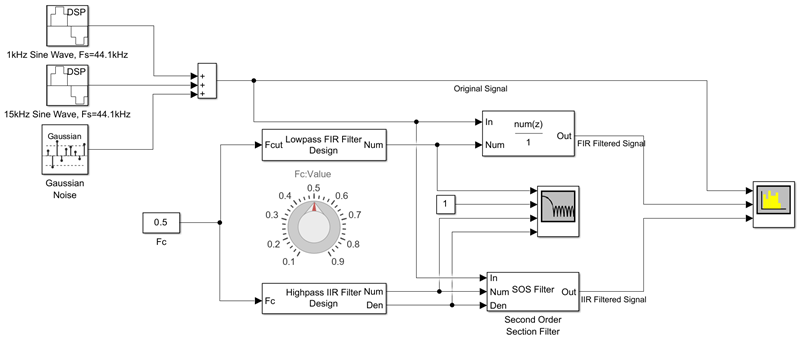
Design and implement FIR and IIR filters with tunable filter specifications using the Tunable FIR and IIR Filters template.
This model shows how to design FIR and IIR filters using the Lowpass FIR Filter Design and the Lowpass IIR Filter Design design blocks. You can tune the filter cutoff frequency using the Knob (Simulink) block. The magnitude response of the designed filters varies as you tune the filter cutoff frequency during simulation. Visualize the magnitude response of the designed filters using the Filter Visualizer block. As with the Basic Filter model template, the input is a noisy sinusoidal signal with tones at 1 kHz and 15 kHz.
The Discrete FIR Filter (Simulink) block and the Second-Order Section Filter block implement a lowpass FIR filter and a highpass IIR filter using the coefficients from the design blocks.
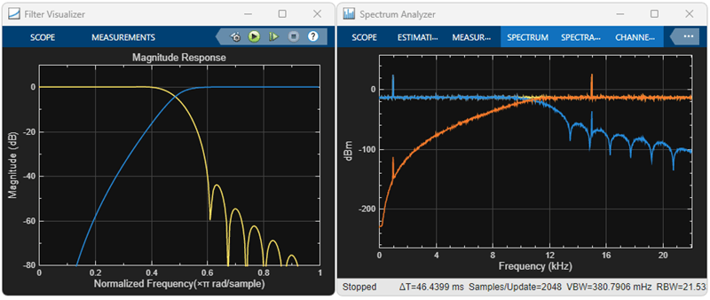
The Filter Visualizer output shows the varying magnitude response of the FIR filter and the IIR filter, and the Spectrum Analyzer output shows the spectra of the original and the filtered signals. In the Spectrum Analyzer output, both tones get attenuated. The 1 kHz tone gets attenuated by the IIR filter and the 15 kHz tone gets attenuated by the FIR filter.
Interpolated FIR Filter
The Interpolated FIR Filter template provides an efficient alternative to a single-stage high-order FIR filter, as it filters the signal at a lower sampling rate. This implementation processes the input signal in multiple stages. A noisy input first passes through an FIR decimator, which lowers the sampling rate of the signal. The signal is then filtered by an FIR filter at this lower sampling rate. An FIR interpolator at the end converts the sampling rate of the filtered output back to its original value.
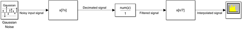
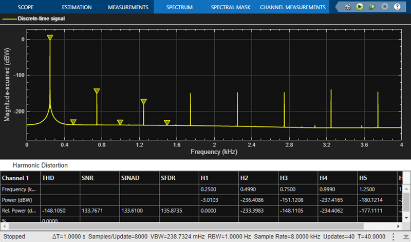
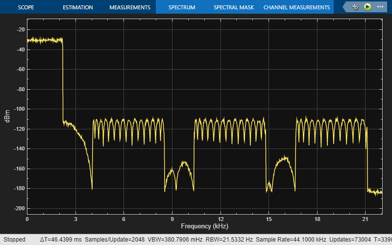
The Spectrum Analyzer block in the model shows the spectrum of the filtered signal.
Mixed-Signal System
Click the Mixed-Signal System template to create a basic A/D converter model configured with settings recommended for DSP System Toolbox and mixed-signal systems. This model performs A/D conversion by implementing an analog anti aliasing filter followed by a zero-order hold circuit. The model acts as a starting point for modeling mixed-signal systems in Simulink using DSP System Toolbox. All discrete-time signals are colored in red to indicate the fastest sample rate. Continuous-time signals are colored in black. For additional sample time options, in the Debug tab, select Information Overlays > Colors.
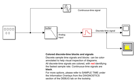
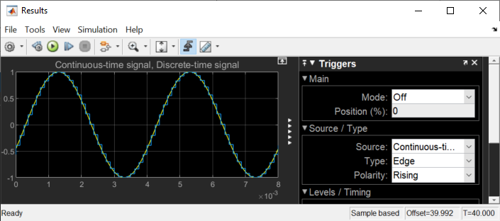
The Scope (Simulink) block in the model plots the continuous-time signal and the discrete-time signal.
The Spectrum Analyzer block shows the spectrum of the discrete-time signal.