Using MCAL ADC and Hardware Interrupt Blocks with Renesas RH850 Microcontrollers
This example shows how to acquire analog signals using the MCAL ADC block in a Simulink® model and process the results using the Hardware Interrupt block on a Renesas RH850/U2A16 starter kit. You can use this approach to generate software-triggered ADC conversions, handle end-of-conversion interrupts, and read multiple ADC channels in real time.
The example demonstrates how to:
Use MCAL DIO Channel Write blocks to generate analog test signals for ADC inputs.
Configure ADC channels and groups using MCAL modules.
Trigger actions using the Hardware Interrupt block when ADC conversions complete.
Read and process ADC conversion results in a triggered subsystem.
This workflow helps you validate ADC configurations, monitor conversion results, and implement real-time signal processing on RH850/U2A microcontrollers.
Prerequisites
Before you begin,
Complete the Simulink Onramp tutorial.
Complete the Hardware Setup for Embedded Coder Support Package for Renesas RH850 Microcontrollers.
Required Hardware
RH850/U2A16 starter kit
Renesas E2 emulator
PC connection cable (USB Type-C)
Hardware Connections
Use jumper wires to make the following connections:
Connect
P10_0toP17_1(ADC Channel_A)Connect
P10_2toP17_3(ADC Channel_B)
Third-Party Configuration Tool
This example uses a third-party configuration tool to generate hardware-accurate, AUTOSAR-compliant settings for MCAL modules, allowing you to focus on application behavior in Simulink rather than low-level device details. In this example, DaVinci Configurator is used to create and validate the MCAL configuration that is later consumed during code generation. For more information on MCAL ADC concepts such as ADC groups, trigger modes, buffer configuration, and hardware versus software triggering, see Getting Started with ADC Using MCAL.
MCAL Configuration Overview
The MCAL configuration for this example is defined in the configuration description file ADCExample.arxml, which is referenced by the model during build.
MCU Module
The MCU module initializes the target and configures system clocks.
Startup and clock configuration are enabled
A 400 MHz system clock is configured
Port Module
The Port module defines pin multiplexing and direction.
P10_0andP10_2are configured as DIO output pins
These pins are used to generate test signals for the ADC inputs.
GPT Module
The GPT module provides the system scheduler.
OSTM0 is configured as the scheduler timer
This configuration supports periodic execution required by the model.
ADC Module
ADCJ1 is used in this example.
Two ADC channels are configured:
ADCChannel_A with channel ID 20
ADCChannel_B with channel ID 22
An ADC Group bundles both channels into a single conversion unit. This group is configured for:
Single access mode
One-shot software triggering
Linear buffer storage
End-of-conversion notification using the function
EOCNotification
The group configuration enables software-triggered, interrupt-driven ADC acquisition.
DIO Module
The DIO module maps digital outputs to physical pins.
Port group 10, bits 0 and 2, are configured as ChannelA and ChannelB
These channels drive known signals into the ADC inputs.
Configuration Description File
The configuration description file provides the link between the AUTOSAR MCAL configuration generated by the third-party tool and the Simulink model used for code generation. The MCAL module configuration for this example is defined in the file ADCExample.arxml. This file contains the configured parameters for the Mcu, Port, Gpt, Dio, and ADC modules, including channel definitions, group settings, and notification callbacks.
Simulink Model
Open the rh850U2AADC.slx Simulink model.
modelName = "rh850U2AADC";
open_system(modelName) 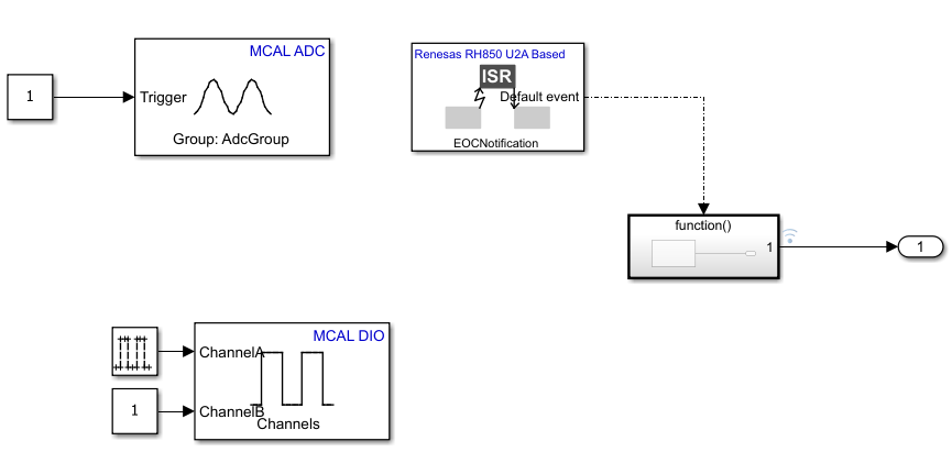
What the model contains:
The MCAL DIO Channel Write block sends a square wave output to ChannelA (P10_0) and a constant high to ChannelB(P10_2).
An MCAL ADC block that triggers ADC conversions
A Hardware Interrupt block that responds to ADC completion
A function-call subsystem that reads and processes ADC results
Configure the Model
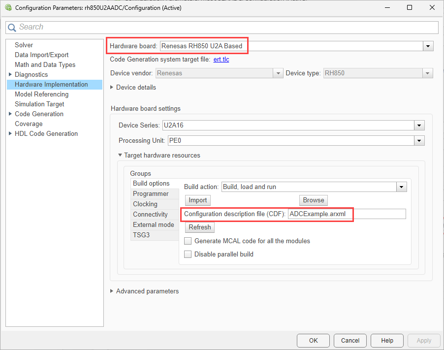
The model is pre-configured for Renesas RH850 U2A Based hardware.
Ensure the following settings are applied:
ADCExample.arxmlis added as the configuration description file in Build options. To verify click Modeling > Model Settings to open the Configuration Parameters dialog box. Navigate to Hardware Implementation > Target hardware resources > Build options.
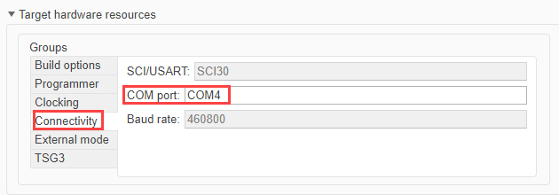
The verify and set the COM port navigate to Hardware Implementation > Target hardware resources > Connectivity.
Configure the Blocks
Software-Triggered Conversion using MCAL ADC block
An MCAL ADC block initiates the conversion.
Double click the MCAL ADC block to open the block parameters dialog.
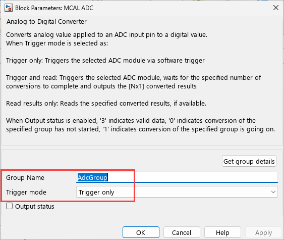
Ensure the following are selected.
The Adc Group is specified as the Group Name.
Trigger onlyis selected as the Trigger mode.
Hardware Interrupt Handling
The Hardware Interrupt block reacts to ADC completion. Double click the Hardware Interrupt block to open the block parameters dialog.
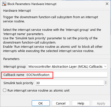
Ensure the following:
The Callback name matches the notification function defined in the configuration description file
In this example, the callback is
EOCNotification.
When the ADC finishes conversion, this interrupt triggers the function-call subsystem.
Reading Conversion Results
Inside the triggered subsystem, another MCAL ADC block reads the results.
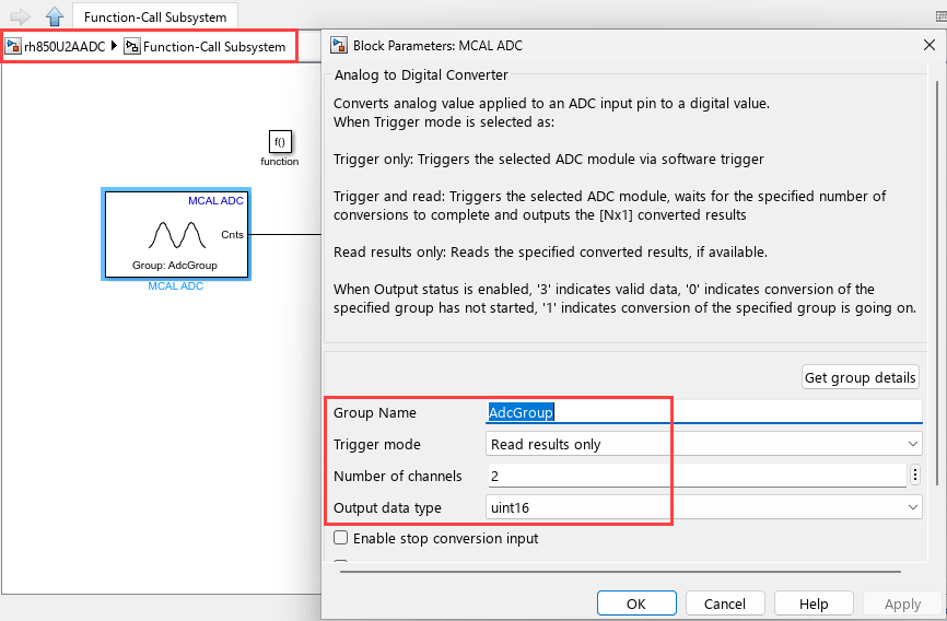
Group Name is set to the configured Adc Group.
Read results only is selected as the trigger mode.
Number of channels is set to 2 for ADCChannel_A and ADCChannel_B.
Output data type is set to
uint16, matching the MCAL definition for the U2A target.
This ensures that ADC data is accessed only after conversion completes.
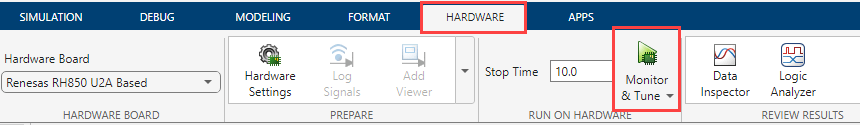
Run Model on Hardware
To deploy and run the model:
1. In the Simulink toolstrip, click Hardware and then click Monitor & Tune.
2. Monitor the build process by opening the Diagnostic Viewer through the link at the bottom of the model canvas.
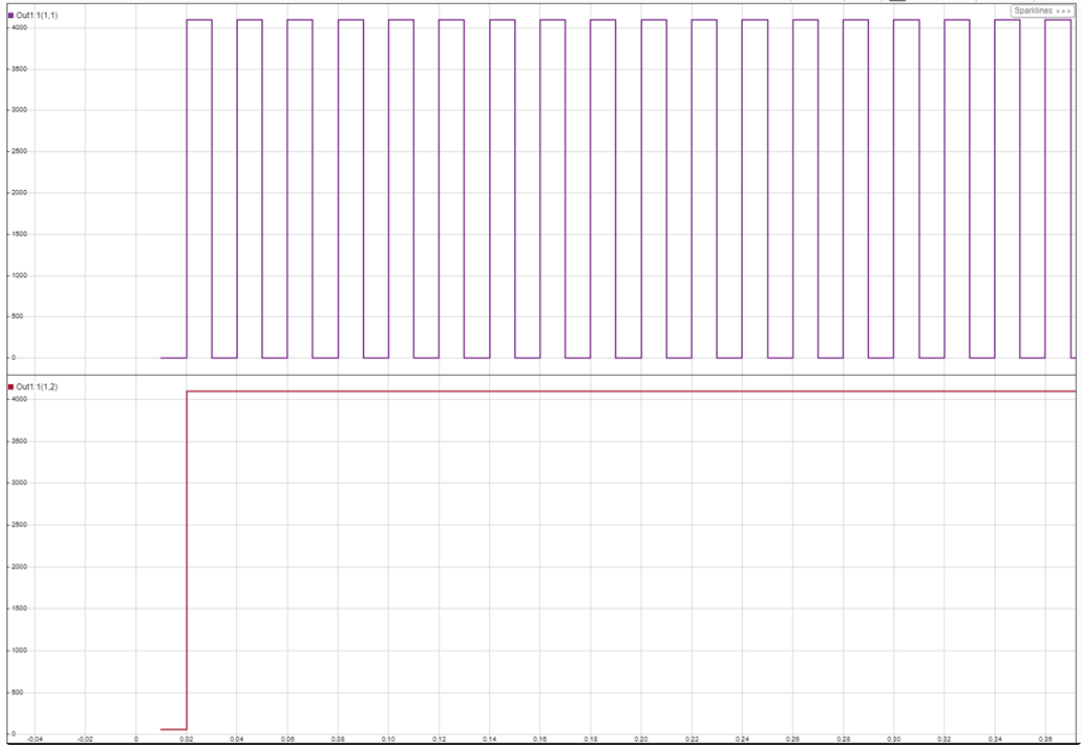
3. After the application runs on hardware, click Data Inspector on the Simulation tab to observe ADC conversion values.
Successful execution confirms correct ADC configuration, interrupt handling, and real-time data acquisition.
Click Monitor & Tune on the Hardware tab to deploy the target model to the hardware.
Use the diagnostic viewer to follow the build progress and wait until the code loads and runs on the target hardware.
Click Data Inspector on the Simulation tab to view the ADC conversion values.