Configure Model Signals, States, and Data Stores with Measurement Service Interface Definitions
R2026bYou can measure a generated-code variable corresponding to a model signal, state, or local data store at run time if the model element is configured as measurable before code generation.
Because the element is configured as measurable, the ASAP2 file generated by the code generator includes a section that describes the model element measurement properties. To learn more about generated ASAP2 files, see:
There are three general types of model elements that can be measured with ASAP2 files:
Local data stores — A model data store is a memory segment stored in a Data Store Memory block. It can be accessed by multiple parts of the model through Data Store Read and Data Store Write blocks. To learn more about local data stores, see Data Stores in Generated Code.
Signals — A model signal stores the data that propagates between model blocks. Root-level inport signals cannot be measured with ASAP2 files. To learn more about model signals, see Configure Signal Data for C Code Generation.
States — A state is a memory segment that represents the internal state of a block. The value of a state is retained between model steps and used in future steps. For example, a Unit Delay block stores its previous output value as a state. To learn more about model states, see Configure Block States for C Code Generation.
Map Model Signals, States, and Data Stores to Measurement Service Interface Definitions
This example shows how to map model elements to measurement services interface definitions for code generation, using a Unit Delay block and its output signal.
To allow measuring these model elements during program execution:
Before generating code, configure the element as measurable and specify its measurement properties.
Generate code for the model.
Generate an ASAP2 file.
Open Explore Model
Open the component model SensorSWC.
soaSensorModel = "SensorSWC";
open_system(soaSensorModel);
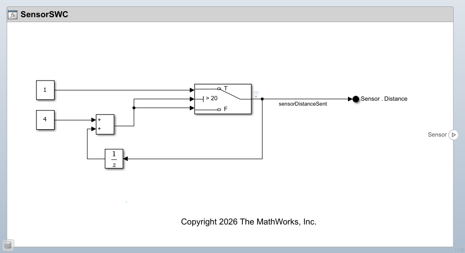
In the example you,
Add measurable model elements to the mappings of the model.
Configure these elements with measurement service interface definitions.
Generate model code that exports the variables corresponding to those elements.
Generate ASAP2 files that contain the description of these elements.
Open Service Mappings Editor
Open the Service Mappings editor by pressing Ctrl+Shift+C. Then, select the Measurements tab.
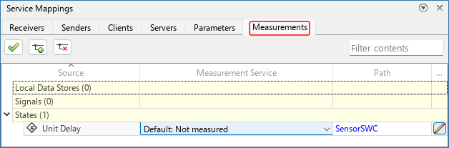
There are three parent entries in the table, each corresponding to one type of measurable model elements. The States entry has a child entry for the Unit Delay block in the model.
Add Signal to Model Mappings
Model signals are not added by default to the model mappings. Select the output signal of the Unit Delay block, and then click the Add selected signals to service mappings button  in the upper left corner of the Service Mappings editor.
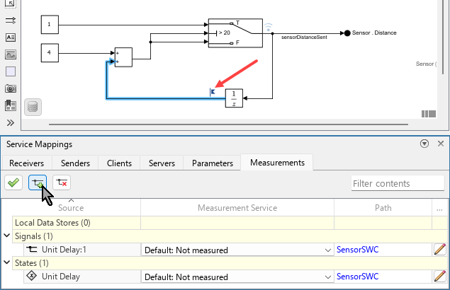
The signal is added as a child entry under the Signals parent entry. A label  appears on the signal line, indicating it is now added to the model mappings.
Configure Measurement Service
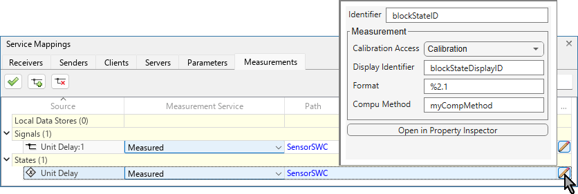
The Measurement Service property determines whether the generated code that represents the measurable model element can be measured during program execution or not. For both the state and signal of the Unit Delay block, set Measurement Service to Measured.
Measurement Properties
When the Measurement Service of a measurable model element is set to Measured, the generated ASAP2 file contains a section that corresponds to the model element and contains the measurement properties of the model element. This allows measurement tools to measure the value of the corresponding variable during program execution. To configure measurement properties of a measurable model element:
Select the Measurements tab of the Service Mappings editor.
In the table, locate the entry of the model element.
Click the pencil icon
 at the end of the entry to open a dialog box in which you configure the measurement properties of the model element.
The Identifier property of the model element is not one of the measurement properties, but you configure it also in the dialog box. Use this property to specify the name of the variable that corresponds to the measured model element, in the code generated from the model. If you leave the Identifier property empty, the name of the corresponding variable is the name of the model element block.
Specify these measurement properties for the Unit Delay state and signal:
block state | block signal | Corresponding Property in ASAP2 File | |
|---|---|---|---|
Identifier |
|
|
|
Calibration Access |
|
| |
Display Identifier |
|
|
|
Format |
| Leave empty |
|
Compu Method |
| Leave empty |
|
Generate Model Code and Calibration File
Generate code from the model.
evalc("slbuild(soaSensorModel,GenerateCodeOnly=true)");
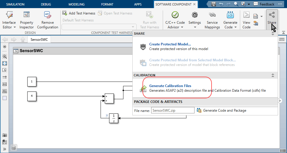
To generate the calibration file, on the Software Component tab of the Simulink Toolstrip, select Share > Generate Calibration Files.
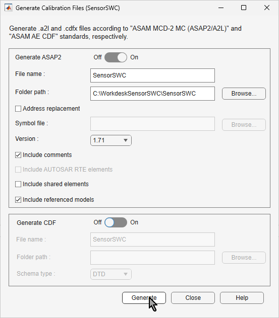
In the Generate Calibration Files dialog box, make sure that Generate ASAP2 switch is set to on and, since you are not using address replacement, make sure the Address replacement is cleared. Then, click Generate.
In the generated file SensorSWC.a2l, locate the sections that correspond to the signal and state of the Unit Delay block. The beginning marker of each of these sections is /begin MEASUREMENT and the end marker is /end MEASUREMENT. Each section consists of the calibration properties of the model element it corresponds to.
  /begin MEASUREMENT
    /* Name                   */      blockSigID
    /* Long identifier        */      ""
    /* Data type              */      FLOAT64_IEEE
    /* Conversion method      */      CM_double
    /* Resolution (Not used)  */      0
    /* Accuracy (Not used)    */      0
    /* Lower limit            */      -1.7E+308
    /* Upper limit            */      1.7E+308
    ECU_ADDRESS                       0x0000 /* @ECU_Address@blockSigID@ */
    DISPLAY_IDENTIFIER blockSigDisplayID
    READ_WRITE
  /end MEASUREMENT

  /begin MEASUREMENT
    /* Name                   */      blockStateID
    /* Long identifier        */      ""
    /* Data type              */      FLOAT64_IEEE
    /* Conversion method      */      myCompMethod
    /* Resolution (Not used)  */      0
    /* Accuracy (Not used)    */      0
    /* Lower limit            */      -1.7E+308
    /* Upper limit            */      1.7E+308
    ECU_ADDRESS                       0x0000 /* @ECU_Address@blockStateID@ */
    DISPLAY_IDENTIFIER blockStateDisplayID
    FORMAT "%2.1"
    READ_WRITE
  /end MEASUREMENT
Note how each of these sections matches the measurement properties of the model element it corresponds to.
See Also
Service Mappings Editor | Measurements Service Interface Properties

