Generate IP Core with an AXI4-Stream Interface
This example shows how to generate an IP core that uses use an AXI4-Stream interface. You can use AXI4-Stream interfaces to enable high-speed data transfer between the processor and FPGA on hardware. In this example, you:
Generate an HDL IP core with an AXI4-Stream interface for a model that uses a simplified streaming protocol.
Integrate the generated IP core into a ZedBoard reference design with DMA controller.
Use the AXI4-Stream IIO Read and IIO Write blocks to generate C code that runs on an ARM processor.
This high-level architecture diagram illustrates the system that you design in this example. The AXI4-Stream interface and direct memory access (DMA) controller, transfer large data chunks from the processor to the FPGA. In the software that runs on the ARM processor, the data is represented as vector data. The DMA controller reads the vector data from memory and streams it to the FPGA IP core through the AXI4-Stream interface. The streaming process sends one data element per sample, because the FPGA IP uses a scalar data type.
The FPGA IP core includes an AXI4-Lite interface for control signals and parameter tuning. The example uses a symmetric FIR filter that operates on the input stream, with filter coefficients as inputs to the model. The model maps coefficients to AXI4-Lite registers, which enables the host computer to tune the parameters.

Prerequisites
This example runs on a ZedBoard. To set up the ZedBoard, see Guided Hardware Setup for AMD Boards. To run this example on a different board, you must select a different target platform in the model. Additionally, you must install Xilinx Vivado® Design Suite. For a list of supported versions, see HDL Language Support and Supported Third-Party Tools and Hardware.
Open and Examine the Model
Open the hdlcoder_sfir_fixed_stream model.
open_system("hdlcoder_sfir_fixed_stream.slx")
set_param("hdlcoder_sfir_fixed_stream","SimulationCommand","Update")

The design under test (DUT) subsystem represents the hardware subsystems that target the FPGA fabric. The Inport blocks x_in_data and x_in_valid, and the Outport blocks y_out_data and y_out_valid, constitute the data path of the filter. The input ports of the subsystem, such as h_in1, are the control ports for tuning the filter parameters.
This model uses the simplified streaming protocol modeling pattern. The symmetric_fir subsystem is an enabled subsystem. The input control signal, x_in_valid manages the enable port of the symmetric_fir subsystem and also drives the output control signal, y_out_valid. For more information about modeling AXI4-Stream interfaces, see Model Design for AXI4-Stream Interface Generation.
Generate HDL IP Core with AXI4-Stream Interface
Next, configure the model for IP core generation, configure the design and target interface, and generate the IP core. This example uses the HDL Code tab in the Simulink® Toolstrip to generate an IP core. You can then deploy the generated IP core to the hardware and connect it to the embedded processor.
Prepare Model for IP Core Generation
First, prepare your model by using the model configuration parameters:
1. Use the hdlsetuptoolpath command to set up the Xilinx Vivado synthesis tool. Use your own Vivado installation path when you run the command.
hdlsetuptoolpath("ToolName","Xilinx Vivado","ToolPath",vivadopath)
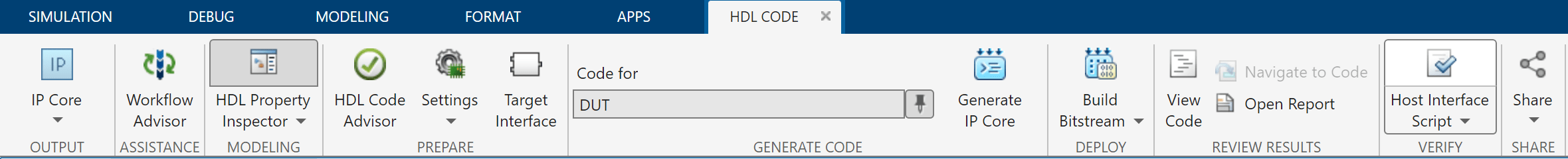
2. In the Apps tab, click HDL Coder. In the HDL Code tab, in the Output section, ensure the drop-down button is set to IP Core. Ensure that Code for is set to the DUT subsystem.
3. Click the Settings button to open the HDL Code Generation > Target pane of the Configuration Parameters dialog box. Set Target Platform to ZedBoard. Ensure the Synthesis Tool is set to Xilinx Vivado and Reference Design is set to Default system with AXI4-Stream interface.
4. Click OK to save your updated settings.
Configure Design and Target Interface
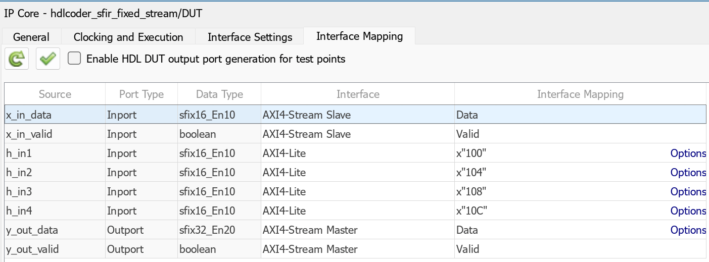
Configure your design to map to the target hardware by mapping the DUT ports to the IP core target hardware and setting DUT-level IP core options. In this example, the input data and valid ports are mapped to an AXI4-Stream Slave interface to receive data from the memory mapped to stream (MM2S) DMA controller, and the output data and valid ports are mapped to an AXI4-Stream Master interface to send data to the stream to memory mapped (S2MM) DMA controller.
In Simulink, in the HDL Code tab, click Target Interface to open the IP Core editor.
Select the Interface Mapping tab. If the mapping table does not appear, click the Reload IP core settings
 button to compile the model and populate the DUT ports and their data types.
Map the
x_in_data,x_in_valid,y_out_data, andy_out_validports to the AXI4-Stream interfaces. Map the control parameter ports, such ash_in1, to the AXI4-Lite interface. Map the DUT ports to the interfaces specified in this image.
4. Validate your settings by clicking the Validate IP core settings ![]() button.
button.
Generate IP Core
Next, generate the IP core. In the Simulink Toolstrip, in the HDL Code tab, click Generate IP Core.
Integrate IP into AXI4-Stream Compatible Reference Design
Insert the generated IP core into an embedded system reference design. To insert the generated IP core, create a project, generate an FPGA bitstream, and download the bitstream to the target hardware.
The reference design is a predefined AMD® Vivado project that contains all the elements the Xilinx software needs to deploy the design to the hardware platform, except for the custom IP core and embedded software. This example uses the HDL Code tab in the Simulink Toolstrip to deploy and verify an IP core.
Create IP Core Project
Integrate the generated IP core into the Xilinx platform by creating a Vivado project that organizes and maintains the files associated with the IP core.
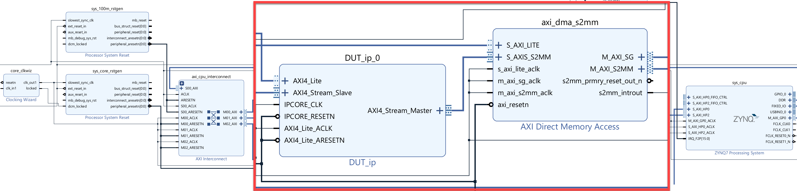
1. To create a Vivado project, in the Simulink Toolstrip, in the HDL Code tab**, select Build Bitstream >** Create IP Core Project. HDL Coder™ inserts the generated IP core into the Default system with AXI4-Stream interface reference design. This reference design contains a Xilinx AXI DMA IP that handles the processor-to-FPGA fabric data streaming.
2. Click the link in the Simulink Diagnostic Viewer to open the generated Vivado project. In Vivado, click Open Block Design to view the Zynq design diagram, which includes the generated HDL IP core, AXI DMA controller, and processor.
3. To generate the bitstream file, in the Simulink Toolstrip, in the HDL Code tab, click Build Bitstream and wait until the synthesis tool runs in the external window.
4. After the bitstream generation finishes, download it by selecting Build Bitstream > Program Target Device.
Generate ARM Executable Using AXI4-Stream Driver Block
To generate the software interface model for the design, in the Simulink Toolstrip, in the HDL Code tab, select Build Bitstream > Software Interface Model. This image shows the generated model.
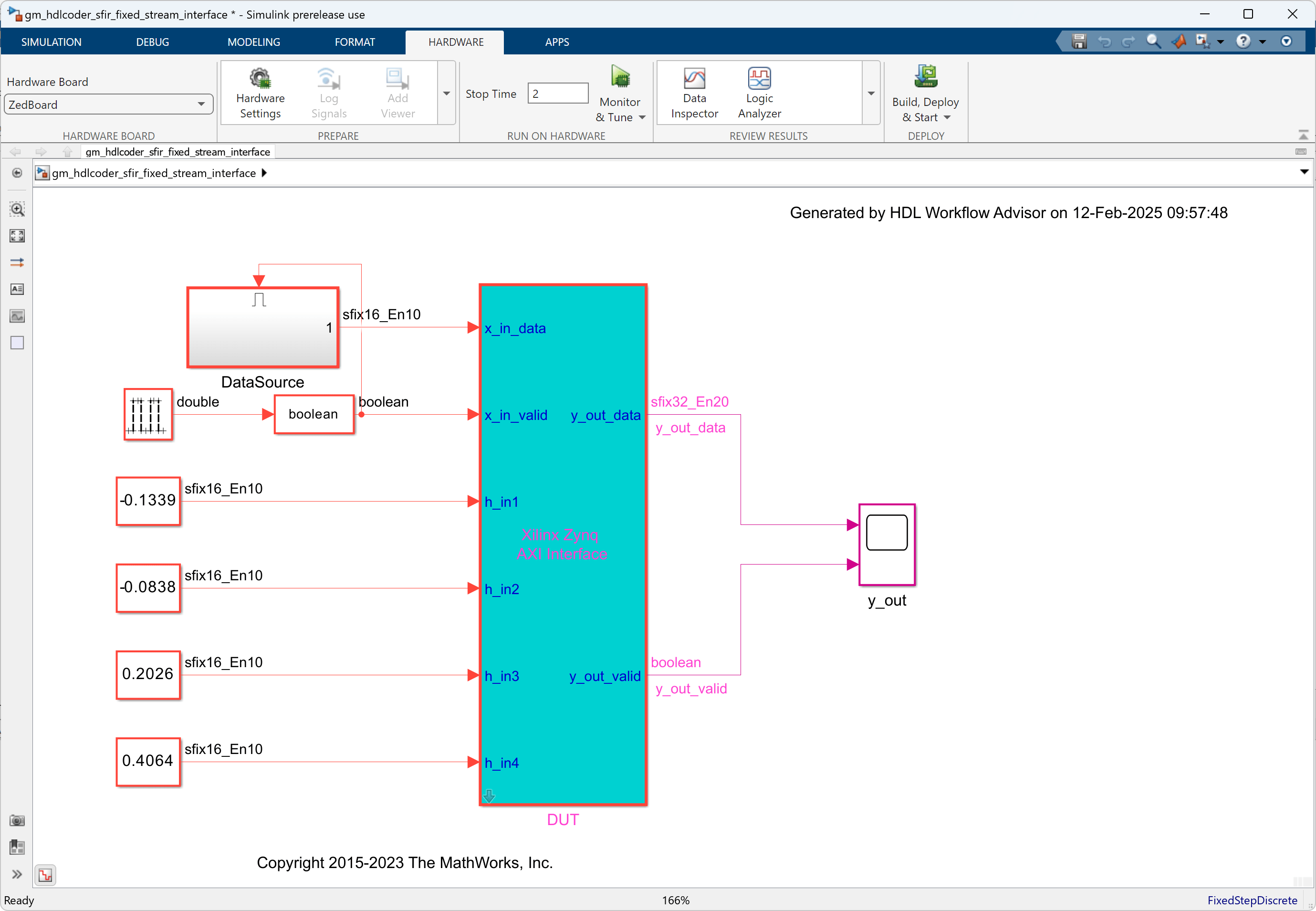
The software interface model generates the AXI4-Lite driver, but it cannot generate the AXI4-Stream driver block. Because it requires a connection to a vector port on the ARM processor, while the x_in_data DUT port is a scalar port.
Before you generate code from the software interface model, open the gm_hdlcoder_sfir_fixed_stream_interface model:
Add the AXI4-Stream IIO Read and AXI4-Stream IIO Write driver blocks, To add the blocks, click Library Browser. In the Library pane, click Embedded Coder Support Package for AMD SoC Devices.
Use a vector data source to drive the x_in_data port.
Connect the x_in_data port to the AXI4-Stream IIO Write driver block.
Double-click the AXI4-Stream IIO Write block and set Timeout to
0.To ensure the AXI4-Stream IIO Write block writes before reading, right-click the block, open Properties, and set Priority to
1.Double-click the AXI4-Stream IIO Read block and set the Frame size to
100, Sample time toTs, and Timeout to10.
You do not need to set the priority for the AXI4-Stream IIO Read block because setting the AXI4-Stream IIO Write block priority to 1 ensures that the write occurs before the read.
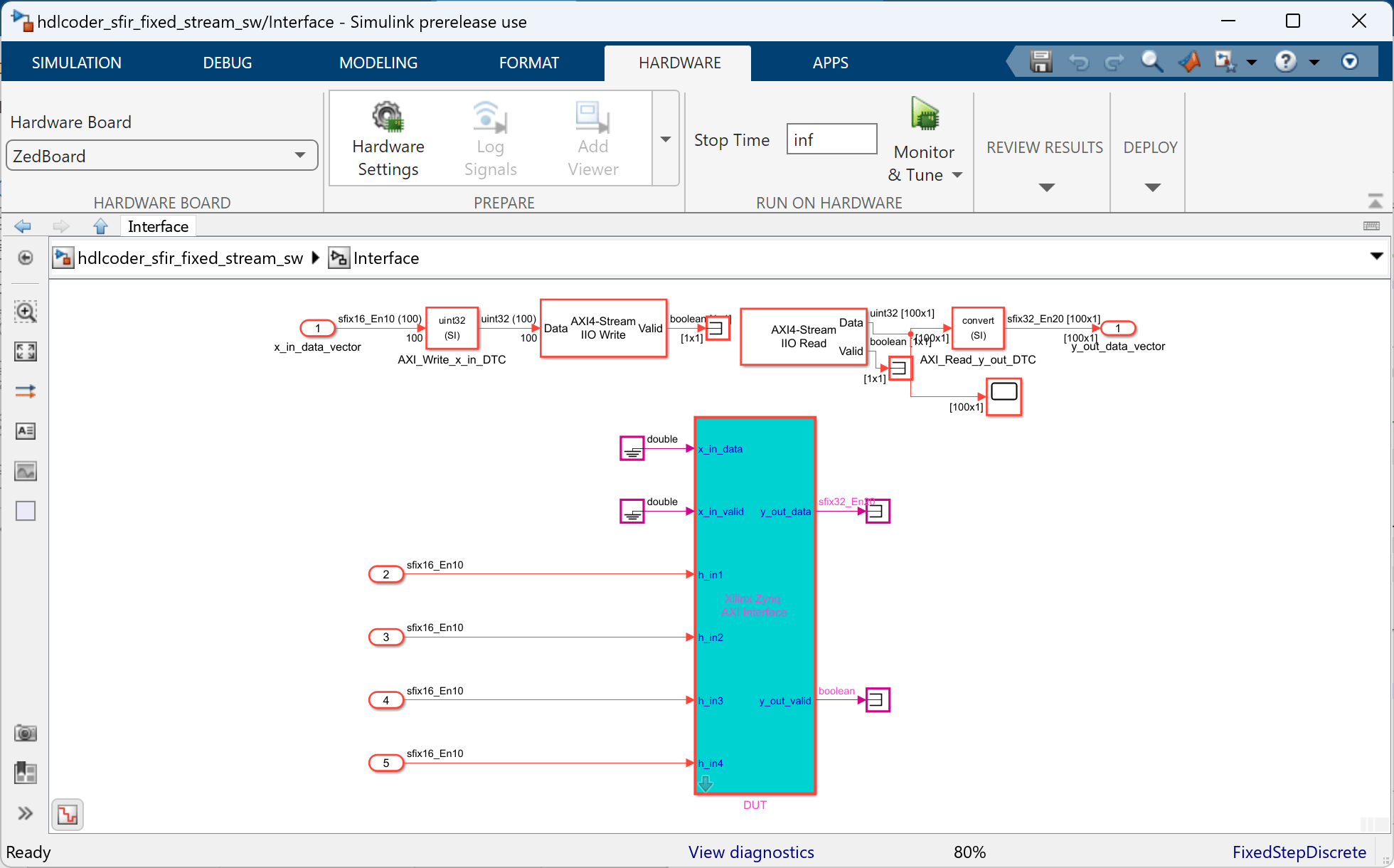
For this example, open the hdlcoder_sfir_fixed_stream_sw model. This model includes the updated software interface.The AXI4-Stream IIO Read and AXI4-Stream IIO Write blocks are in the hdlcoder_sfir_fixed_stream_sw/Interface subsystem. A vector data source with 100 data elements is the input to the AXI4-Stream DMA driver block. This model streams 100 32-bit data samples from the DMA controller to the HDL IP core via the AXI4-Stream interface for each processor sample time, and receives 100 32-bit streaming data samples.
Configure and build the software interface model for external mode:
Click the Hardware tab, click Hardware Settings to open the Configuration Parameter dialog box.
In the Solver pane, set Stop Time to
inf. Click OK.In the Hardware tab, click Monitor and Tune.
Run the model. Embedded Coder builds the model, downloads the ARM executable to the ZedBoard hardware, executes it, and connects the model to the executable running on the ZedBoard hardware.
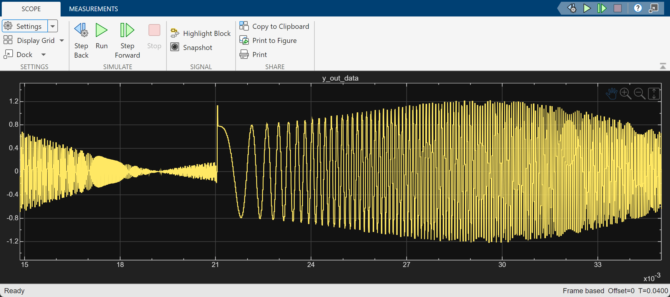
Open the Scope block, y_out, to observe the output of the FIR filter IP core from the Zynq hardware. The hardware and software parts of the design run on the Zynq hardware. The ARM processor sends the source data to the FPGA IP through the DMA controller and the AXI4-Stream interface. The ARM processor receives the filter result data from the FPGA IP and sends the result data to Simulink via external mode.
Tune the FIR filter parameters in the software interface model and observe how the output changes. For example, double-click the Constant block with a value of -0.0838 and change Constant value to 0.6.
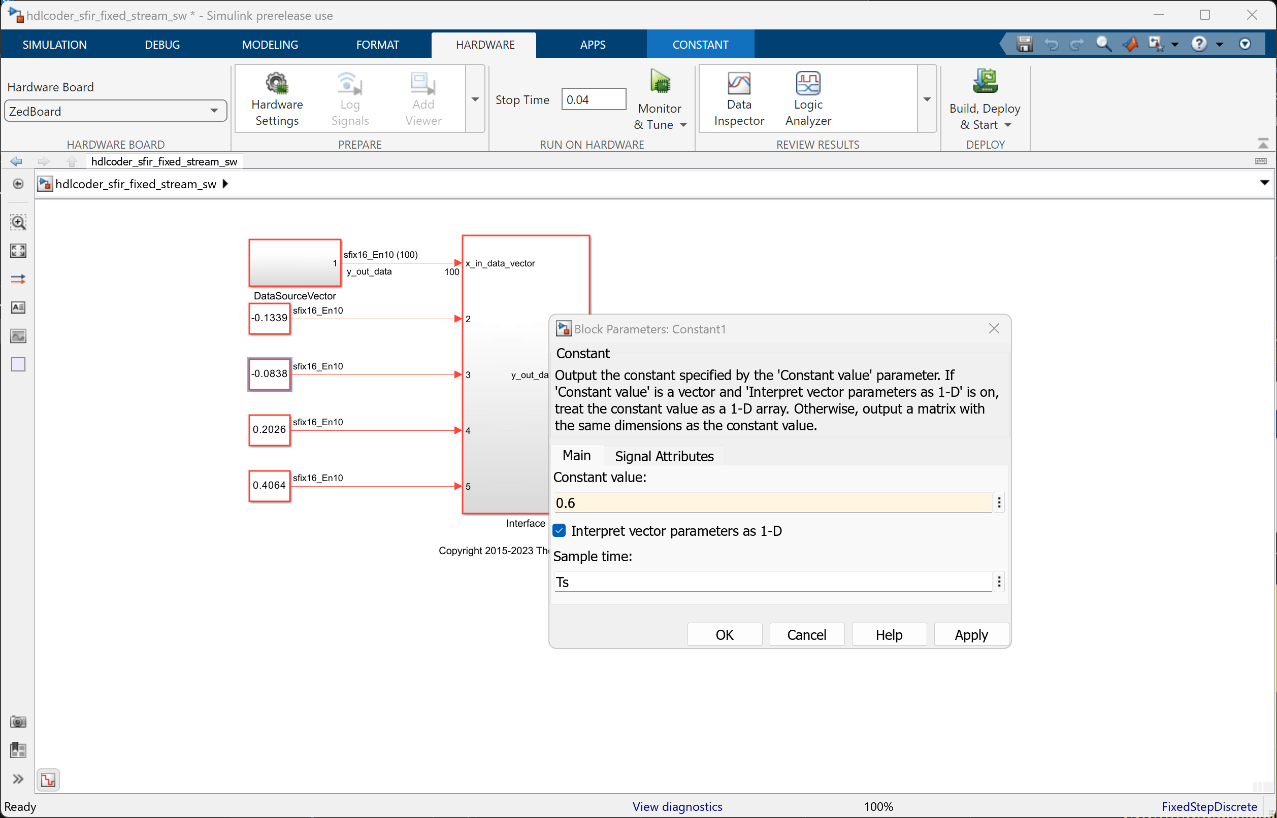
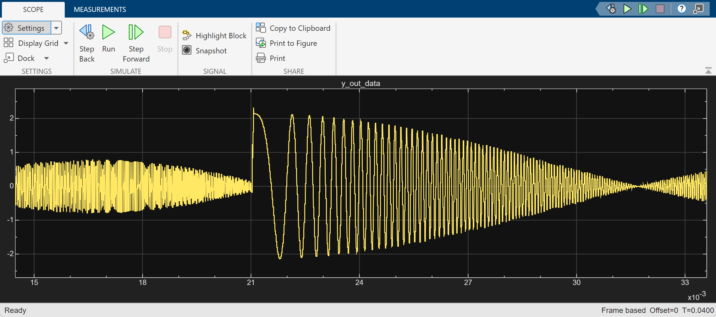
Run the simulation again and observe the change in output.
See Also
Blocks
- AXI4-Stream IIO Write (Embedded Coder) | AXI4-Stream IIO Read (Embedded Coder)