Deploy HLS IP Core for Image Convolution on Zynq with DDR Access
R2026bYou can generate an IP core with AXI4 Master interfaces by using the HDL Coder™ HLS IP Core Generation workflow. The AXI4 Master protocol enables communication between your design and the external memory controller IP. This example shows how to create an IP core with an AXI4 Master interface for designs that need to access large data sets stored in external or shared memory.
Introduction
This example demonstrates a convolution algorithm implemented on a ZedBoard. The design uses AXI4 Master interfaces to store matrices in the shared DDR memory and perform direct read and write operations because the input matrix cannot be efficiently mapped to on-chip RAM. This approach is well-suited for applications that require large-scale data processing or frequent DDR access. You can also target other platforms with reference design architectures mentioned in Default System Reference Design for AMD SoC Devices.
In this example, you can:
Convert the MATLAB® convolution algorithm to synthesizable C++ code using HDL Coder™.
Perform C-synthesis and generate an HLS IP core with AXI4 Master interface.
Access large input matrices from shared DDR memory on the ZedBoard, perform convolution in the IP core, and write the result back to the shared DDR using the AXI4 Master.
Deploy the IP core on Zynq hardware and prototype using FPGA I/O Host Interface Scripts.
Additionally, the algorithm supports run-time configuration of kernel coefficients through AXI4-Lite registers. To get started with the HLS IP core workflow, see Get Started with HLS IP Core Generation Workflow (HDL Coder).
Requirements
Xilinx Vivado Design Suite, with a supported version listed in the HDL Language Support and Supported Third-Party Tools and Hardware (HDL Coder).
Xilinx Vitis HLS, with a supported version listed in the HDL Language Support and Supported Third-Party Tools and Hardware (HDL Coder).
Set up the ZedBoard. For more information, see the section Set Up Zynq Hardware and Tools in Get Started with IP Core Generation from Simulink Model (HDL Coder).
Model Convolution Algorithm for Memory Mapping
The mlhdlc_hlsipcore_convolution_2D function performs a 2-D convolution with configurable kernel coefficients on an RGB image (rgbImage) and returns the processed output image (result). The input and output are mapped to the AXI4 Master interface, which enables read and write access to DDR memory.
Stencil operations apply the same computation pattern across different regions of an input array to produce an output array. Each output element is computed using a fixed-size window of neighboring input elements. In the mlhdlc_hlsipcore_convolution_2D function, the computation loops use predictable offsets (xoffset, yoffset), which allows Xilinx Vitis HLS to apply stencil optimizations. To enable this, the function includes the coder.hdl.literaltext pragma:
coder.hdl.literaltext("#pragma HLS array_stencil variable=rgbImage")
The array_stencil pragma is a specific optimization directive in Xilinx Vitis HLS that improves the hardware implementation of stencil operations by:
Detecting and optimizing memory access patterns for sliding window operations.
Creating efficient caching mechanisms to reduce redundant DDR reads.
Enabling parallel processing for stencil computations wherever possible.
Consider these when generating an IP core:
The stencil pragma must be placed within the loop.
The loop where stencil optimization is applied requires a pipeline pragma with
II=1.Stencil optimization requires nested loops to be perfectly nested loops and have a fixed pattern.
Generated code must be in row-major memory layout.
For more information, see the Xilinx Vitis HLS documentation on the HLS array stencil pragma.
Open the mlhdlc_hlsipcore_convolution_2D function to see how it performs 2-D image convolution.
type mlhdlc_hlsipcore_convolution_2D.m%%%%%%%%%%%%%%%%%%%%%%%%%%%%%%%%%%%%%%%%%%%%%%%%%%%%%%%%%%%%%%%%%%%%%%%%%%%%%%%
% MATLAB design: 2-D convolution
%
% Introduction: This function implements a 2-D convolution filter algorithm on
% an image using a specified kernel (filter coefficients), enabling operations
% such as blurring, edge detection, and so on, with optimizations for
% hardware implementation.
%
%%%%%%%%%%%%%%%%%%%%%%%%%%%%%%%%%%%%%%%%%%%%%%%%%%%%%%%%%%%%%%%%%%%%%%%%%%%%%%%
% Input: rgbImage - the RGB Image
% 2-D array
% kernel - coefficients to specify the type of filtering
% 1-D array
% kernel_size - size of kernel
% 1-D array (compile-time constant)
%
% Output: result - convolved image
% 2-D array
% Copyright 2025 The MathWorks, Inc.
function result = mlhdlc_hlsipcore_convolution_2D(rgbImage,kernel,kernel_size)
[image_height, image_width] = size(rgbImage);
filter_height = kernel_size(1);
filter_width = kernel_size(2);
% Reshape the kernel from 1-D to 2-D
kernel_reshape = reshape(kernel, filter_height, filter_width);
factor = 1.0/(filter_height*filter_width);
bias = 0;
kernel1 = coder.nullcopy(kernel_reshape);
for i = 1:filter_height
for j = 1:filter_width
coder.hdl.literaltext("#pragma HLS pipeline II=1")
kernel1(i,j) = kernel_reshape(i,j);
end
end
result = coder.nullcopy(rgbImage);
for y = 1:image_height
for x = 1:image_width
coder.hdl.literaltext("#pragma HLS pipeline II=1")
coder.hdl.literaltext("#pragma HLS array_stencil variable=rgbImage")
sum = zeros(1,1,'int32');
for row = 1:filter_height
for col = 1:filter_width
xoffset = (x + col - floor(filter_width/2));
yoffset = (y + row - floor(filter_height/2));
if ~(xoffset < 1 || xoffset > image_width || yoffset < 1 || yoffset > image_height)
% clamp pixels to 0 when outside of image
pixel = rgbImage(yoffset,xoffset);
sum = cast(pixel*kernel1(row,col),'like',sum) + sum;
end
end
end
outPixel = cast(min(max(factor*sum + bias, 0),255),'like',result);
result(y,x) = outPixel;
end
end
end
The test bench provides input conditions to validate the convolution algorithm.
type mlhdlc_hlsipcore_convolution_2D_tb.m%%%%%%%%%%%%%%%%%%%%%%%%%%%%%%%%%%%%%%%%%%%%%%%%%%%%%%%%%%%%%%%%%%%%%%%%%%%
% MATLAB test bench for convolution_2D
%%%%%%%%%%%%%%%%%%%%%%%%%%%%%%%%%%%%%%%%%%%%%%%%%%%%%%%%%%%%%%%%%%%%%%%%%%
% Copyright 2025 The MathWorks, Inc.
% Load your image
image = imread('mlhdlc_hlsipcore_convolution_2D_img.png');
% Define convolution kernel (filter)
kernel = ones(5,5);
% Reshape kernel to 1D array
kernel_reshape = reshape(kernel,1,5*5);
% Separate color channels
redChannel = image(:,:,1);
greenChannel = image(:,:,2);
blueChannel = image(:,:,3);
convolvedRGBImage_red = mlhdlc_hlsipcore_convolution_2D(redChannel,kernel_reshape,size(kernel));
convolvedRGBImage_green = mlhdlc_hlsipcore_convolution_2D(greenChannel,kernel_reshape,size(kernel));
convolvedRGBImage_blue = mlhdlc_hlsipcore_convolution_2D(blueChannel,kernel_reshape,size(kernel));
% Combine the convolved channels
convolvedRGBImage = cat(3, convolvedRGBImage_red, convolvedRGBImage_green, convolvedRGBImage_blue);
Create MATLAB HDL Coder Project
In the MATLAB Command Window, enter this command to create an HDL Coder project and open the HDL Workflow Advisor.
coder -hdlcoder -new convolution_2D
In the HDL Workflow Advisor, configure these tasks:
In the HDL Workflow Advisor task, set Code Generation Workflow to
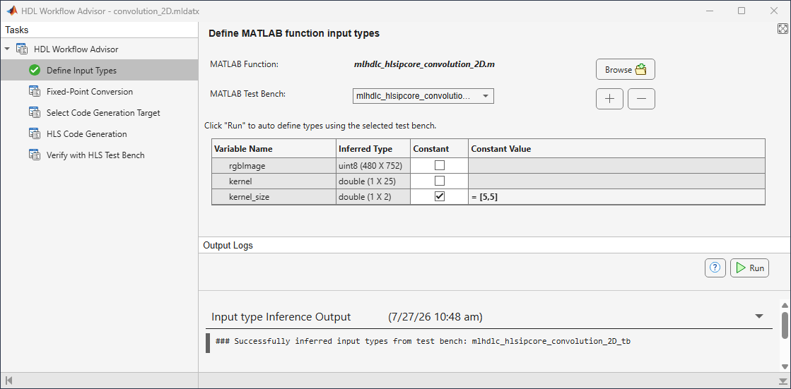
MATLAB to HLS.In the Define Input Types task:
For MATLAB Function, click Browse and select
mlhdlc_hlsipcore_convolution_2D.For MATLAB Test Bench, click the + button and select
mlhdlc_hlsipcore_convolution_2D_tb.Click Run to automatically define types using the selected test bench.
For the Variable Name
kernel_size, select the check box Constant and set the Constant Value to[5,5].
Define Code Generation Target
Generate a shareable and reusable IP core using the HDL Workflow Advisor. HDL Coder integration with the Xilinx Vivado IDE helps incorporate the generated IP core into the FPGA design.
To generate the IP core using the HDL Workflow Advisor:
In the HDL Workflow Advisor, click Select Code Generation Target.
Set Workflow to
IP Core Generation.Set Platform to
ZedBoard.Set Synthesis tool to
Xilinx Vivado.Set Target Frequency (MHz) to
100.Under IP core settings, set Reference design to
Default systemand Processor/FPGA synchronization toFree running(default). For more information, see Processor and FPGA Synchronization (HDL Coder).
Map Interface to Input and Output Ports
To map your MATLAB design function to the hardware, go to the Set Target Interface task. In the Ports tab, assign these values to the Target Platform Interface column for input and output ports.
Set
rgbImagetoAXI4 Master Read.Set
kerneltoAXI4-Lite.Set
resulttoAXI4 Master Write.
Xilinx Vitis HLS generates AXI4-accessible registers for these ports. You can use MATLAB to tune these parameters at run-time when the design is running on the target platform.
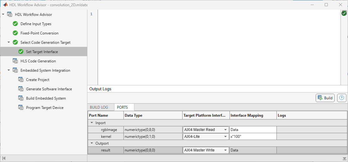
The AXI4 Master interface provides separate channels to read and write data. In this design, the DUT reads input data from DDR memory through the AXI4 Master Read channel, performs the convolution operation, and writes the processed output back to DDR through the AXI4 Master Write channel.
When you map I/O ports to AXI4 Master Read/Write interfaces, HDL Coder automatically generates the corresponding TCL directives in the syn_script.tcl file. You can access this script through the link provided in the IP core report.
The AXI4 Master interface includes address channels that allow reading and writing to specific memory locations. By default, the AXI4 Master interface starts all read and write operations from the address 0x00000000. Xilinx Vitis HLS creates offset registers for both AXI4 Master Read and Write channels. These registers allow overriding the default base address at run time, enabling access to different memory regions. The mapping of these offset registers is generated in the header file, which is linked in the generated HLS IP core report. For more information on the address mapping, see the Register Address Mapping section of the generated HLS IP core report.
Generate and Integrate IP Core with Xilinx Vivado Environment
To generate the IP core, go to the HLS Code Generation task and on the Advanced tab, set Array Layout to Row Major.
Right-click the HLS Code Generation task and select Run This Task. This step generates synthesizable C++ code from the MATLAB function and synthesizes it into an IP core using Xilinx Vitis HLS. HDL Coder generates an HLS IP core report that includes links to all the generated files and details about address mapping and targeting.
Right-click the Create Project subtask and select Run This Task to generate the Vivado project. During the project creation, the generated DUT IP core is integrated into the default system with Shared Memory Access reference design. The generated IP core gets access to the shared DDR through the high-performance AXI bus. You can view the Vivado project by clicking the project link in the result window and inspect the design.
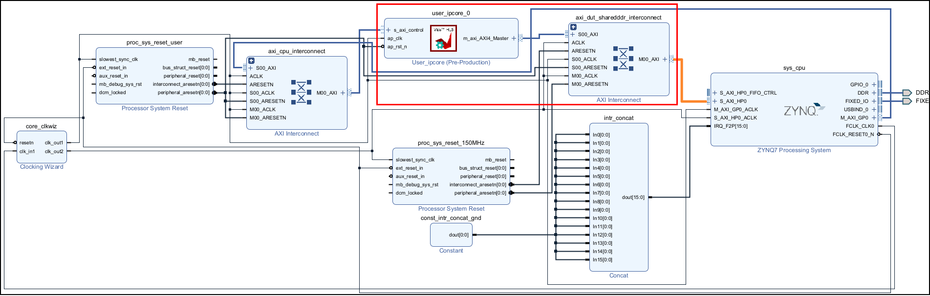
Right-click the Generate Software Interface subtask and select Run This Task to generate setup and interface scripts. Use these files to verify your generated IP core on the ZedBoard hardware. These files contain commands that you can use to connect to your hardware and interact with the IP core. For more information, see Generate and Manage FPGA I/O Host Interface Scripts (HDL Coder).
After bitstream generation completes, right-click the Program Target Device subtask and select Run This Task to deploy on the ZedBoard.
Run and Verify IP Core on Zynq Hardware
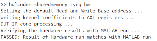
Run the FPGA implementation and verify the hardware result by running the following script in MATLAB.
hdlcoder_sharedmemory_zynq_hw
The script configures the base addresses of the AXI4 Master read and write channels by writing read/write base addresses to the corresponding AXI4 registers. These addresses define the base address that the DUT reads from and writes to external DDR memory. In this example, the DUT reads from address 10000000 and writes to address 14000000.
The DUT IP core reads input data from the DDR memory, performs convolution, and writes the result back to the DDR memory.
The output is read back to MATLAB and compared with the expected value. This verifies the hardware results in MATLAB.
See Also
coder.hdl.literaltext (HDL Coder) | coder.rowMajor (MATLAB Coder)

