Enhanced Edge Detection from Noisy Color Video
R2026bThis example shows how to develop a complex pixel-stream video processing algorithm, accelerate its simulation using MATLAB® Coder™, and generate HDL code from the design. The algorithm enhances the edge detection from noisy color video.
You must have a MATLAB Coder license to run this example.
This example builds on the Pixel-Streaming Design in MATLAB (Vision HDL Toolbox) and the Accelerate Pixel-Streaming Designs Using MATLAB Coder (Vision HDL Toolbox) examples.
Test Bench
In the EnhancedEdgeDetectionHDLTestBench.m file, the videoIn object reads each frame from a color video source, and the imnoise function adds salt and pepper noise. The test bench passes this noisy color image to the frm2pix object, which converts the full image frame to a stream of pixels and control structures. The function EnhancedEdgeDetectionHDLDesign.m then processes one pixel and its associated control structure at a time. After the design processes the entire pixel-stream and collects the output stream, the pix2frm object converts the output stream to full-frame video. The full-frame reference design EnhancedEdgeDetectionHDLReference.m also processes the noisy color image. The test bench compares its output to that of the pixel-stream design. The function EnhancedEdgeDetectionHDLViewer.m displays video outputs.
The workflow above is implemented in the following lines of EnhancedEdgeDetectionHDLTestBench.m.
...
frmIn = zeros(actLine,actPixPerLine,3,'uint8');
for f = 1:numFrm
    frmFull = readFrame(videoIn);             % Get a new frame
    frmIn = imnoise(frmFull,'salt & pepper'); % Add noise
     % Call the pixel-stream design
     [pixInVec,ctrlInVec] = frm2pix(frmIn);
     for p = 1:numPixPerFrm
         [pixOutVec(p),ctrlOutVec(p)] = EnhancedEdgeDetectionHDLDesign(pixInVec(p,:),ctrlInVec(p));
     end
     frmOut = pix2frm(pixOutVec,ctrlOutVec);
     % Call the full-frame reference design
     [frmGray,frmDenoise,frmEdge,frmRef] = EnhancedEdgeDetectionHDLReference(frmIn);
     % Compare the results
     if nnz(imabsdiff(frmRef,frmOut))>20
         fprintf('frame %d: reference and design output differ in more than 20 pixels.\n',f);
         return;
     end
     % Display the results
     EnhancedEdgeDetectionHDLViewer(actPixPerLine,actLine,[frmGray frmDenoise uint8(255*[frmEdge frmOut])],[frmFull frmIn]);
 end
 ...
Because frmGray and frmDenoise are uint8 data type while frmEdge and frmOut are logical, uint8(255*[frmEdge frmOut]) maps logical false and true to uint8(0) and uint8(255), respectively, so that matrices can be concatenated.
Both frm2pix and pix2frm are used to convert between full-frame and pixel-stream domains. The inner for-loop performs pixel-stream processing. The rest of the test bench performs full-frame processing.
Before the test bench terminates, the test bench displays the frame rate to show the simulation speed.
For the functions that do not support C code generation, such as tic, toc, imnoise, and fprintf in this example, use coder.extrinsic to declare them as extrinsic functions. The code generator excludes extrinsic functions from MEX generation. The simulation executes them in the regular interpreted mode. Because the C code generation process does not include imnoise, the compiler cannot infer the data type and size of frmIn. To fill in this missing piece, add the statement frmIn = zeros(actLine,actPixPerLine,3,'uint8') before the outer for-loop.
Pixel-Stream Design
The function defined in EnhancedEdgeDetectionHDLDesign.m accepts a pixel stream and a structure consisting of five control signals, and returns a modified pixel stream and control structure. For more information on the streaming pixel protocol used by System objects from the Vision HDL Toolbox, see the Streaming Pixel Interface (Vision HDL Toolbox).
In this example, the rgb2gray object converts a color image to grayscale, medfil removes the salt and pepper noise, and sobel highlights the edges. Finally, the mclose object performs morphological closing to enhance the edge output. The following code shows this processing.
[pixGray,ctrlGray] = rgb2gray(pixIn,ctrlIn);         % Convert RGB to grayscale
[pixDenoise,ctrlDenoise] = medfil(pixGray,ctrlGray); % Remove noise
[pixEdge,ctrlEdge] = sobel(pixDenoise,ctrlDenoise);  % Detect edges
[pixClose,ctrlClose] = mclose(pixEdge,ctrlEdge);     % Apply closing
Full-Frame Reference Design
When designing a complex pixel-stream video processing algorithm, develop a parallel reference design using functions from the Image Processing Toolbox™. These functions process full image frames. Such a reference design helps verify the implementation of the pixel-stream design by comparing the output image from the full-frame reference design to the output of the pixel-stream design.
The function EnhancedEdgeDetectionHDLReference.m contains a similar set of four functions as in the EnhancedEdgeDetectionHDLDesign.m. The key difference is that the functions from Image Processing Toolbox process full-frame data.
Because of the implementation difference between the edge function and the visionhdl.EdgeDetector System object, the reference and design outputs match if frmOut and frmRef differ in no more than 20 pixels.
Create MEX File and Simulate the Design
Generate and execute the MEX file.
codegen('EnhancedEdgeDetectionHDLTestBench');Code generation successful.
EnhancedEdgeDetectionHDLTestBench_mex;
frame 1: reference and design output differ in more than 20 pixels.
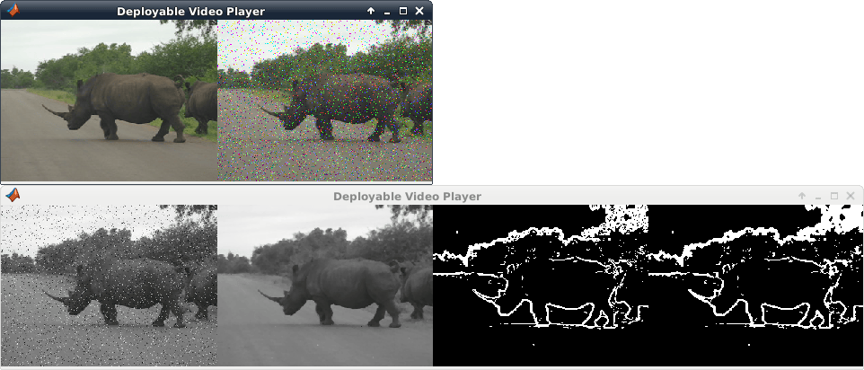
The upper video player displays the original color video on the left, and its noisy version after adding salt and pepper noise on the right. The lower video player, from left to right, shows: the grayscale image after color space conversion, the de-noised version after median filter, the edge output after edge detection, and the enhanced edge output after morphological closing operation.
In the lower video chain, only the pixel-stream design generates the enhanced edge output (right-most video). The other three are the intermediate videos from the full-frame reference design. To display all of the four videos from the pixel-stream design, write the design file to output four sets of pixels and control signals, and instantiated three more visionhdl.PixelsToFrame objects to convert the three intermediate pixel streams back to frames. For simulation speed and the clarity of the code, this example does not implement the intermediate pixel-stream displays.
HDL Code Generation
To generate HDL code for this design, use the HDL Workflow Advisor.
In the MATLAB Editor, on the Apps tab, select HDL Coder. Create a project and set MATLAB Function to
EnhancedEdgeDetectionHDLDesign.mand MATLAB Test Bench toEnhancedEdgeDetectionHDLTestBench.m.Right-click the HDL Code Generation task and select Run to selected task.
After code generation completes, the report opens. Examine the generated HDL code in the report.
For the full workflow, see Generate HDL Code from MATLAB Algorithms.

