Positive-Displacement Compressor (2P)
Libraries:
Simscape /
Fluids /
Two-Phase Fluid /
Fluid Machines
Description
The Positive-Displacement Compressor (2P) block represents a positive-displacement compressor, such as a reciprocating piston, rotary screw, rotary vane, or scroll, in a two-phase fluid network. Port R and port C are mechanical rotational conserving ports associated with the compressor shaft and casing, respectively. When there is positive rotation at port R with respect to port C, two-phase fluid flows from port A to port B. The block may not be accurate for reversed flow.
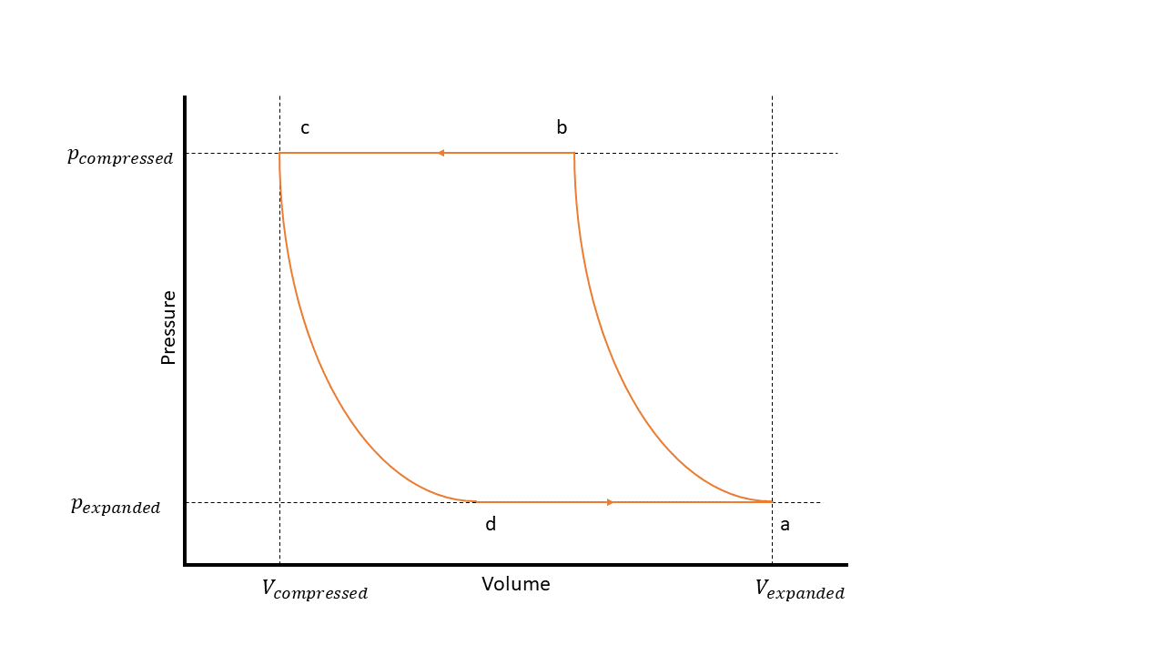
The figure shows the steps of a positive-displacement compressor on a P-V diagram, which has these states:
a — The compressor cylinder is full at inlet pressure.
b — The pressure inside the compressor exceeds that of the outlet, which results in fluid discharge.
c — The compressor reaches the top of the piston stroke, and only the clearance volume remains in the cylinder.
d — The pressure inside the cylinder drops below the inlet pressure, which results in fluid intake.
Mass Flow Rate
The block calculates the mass flow rate as
where:
ṁ is the mass flow rate.
ω is the angular velocity of port R relative to port C.
vs is the specific volume at the inlet. The block calculates this value based on the Nominal conditions specification parameter and specified nominal inlet conditions.
Vdisp is the displacement volume that the block uses.
Displacement Volume
When you set Displacement specification to Volumetric
displacement, the block uses the Displacement
volume parameter as the value for
Vdisp.
When you set Displacement specification to
Nominal mass flow rate and shaft speed, the block
calculates the displacement volume as
where:
ṁnominal is the value of the Nominal mass flow rate parameter.
ωnominal is the value of the Nominal shaft speed parameter.
ηVnominal is the value of the Nominal volumetric efficiency parameter when the Efficiency specification parameter is
Analytical. When the Efficiency specification parameter isTabulated, the block uses thetablelookupfunction to interpolate ηVnominal as a function of the shaft speed and the pressure ratio.
Volumetric Efficiency
You can parameterize the volumetric efficiency by using analytical values or a lookup table.
When you set Efficiency specification to
Analytical, the block calculates the volumetric
efficiency by using analytical values. When the Thermodynamic
model parameter is Polytropic, the
volumetric efficiency is
where pin and pout are the inlet and outlet pressures, respectively, and n is the value of the Polytropic exponent parameter. The block calculates the clearance volume fraction, C, as
where ηVnominal is the value of the Nominal volumetric efficiency parameter and pratio is the value of the Nominal pressure ratio parameter.
When the Thermodynamic model parameter is
Isentropic, the volumetric efficiency is
where vin and vout are the inlet and outlet specific volumes, respectively. The block calculates the clearance volume fraction, C, as
where is the nominal specific volume ratio. The block calculates this value from the nominal inlet conditions and the isentropic efficiency depending on the choice for the Nominal conditions specification parameter.
When you set Efficiency specification to
Tabulated, the block calculates the volumetric
efficiency by interpolating the values of the Volumetric efficiency
table, eta_vol(pr,w) parameter as a function of the shaft speed
and the pressure ratio.
Continuity Equations
The block conserves mass such that
where ṁA and ṁB are the mass flow rates at ports A and B, respectively. The block conserves energy such that
where Δht is the change in specific total enthalpy and ṁAΔht is the fluid power, which is equal to the mechanical power, torque*ω.
When the Thermodynamic model parameter is
Polytropic, the fluid power is
where the block uses the polytropic relationship to relate pin, pout, vin, and vout.
When the Thermodynamic model parameter is
Isentropic, the fluid power is
The block calculates
Δht from the isentropic efficiency,
ηisen. When Efficiency
specification is Analytical,
ηisen is equal to the value of the
Isentropic efficiency parameter. When Efficiency
specification is Tabulated, the block
calculates ηisen by interpolating the
values of the Isentropic efficiency table, eta_isen(pr,w)
parameter as a function of the pressure ratio and the shaft speed.
Visualizing the Volumetric Efficiency
To visualize the block volumetric efficiency, in the block dialog box, click the Plot button next to Volumetric efficiency. Each time you modify the block settings, click Reload Data in the figure window.
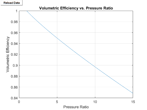
When you set Efficiency specification to
Analytical and Thermodynamic
model to Polytropic, the block plots the
compressor volumetric efficiency against the pressure ratio.
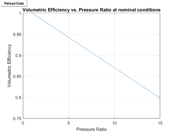
When you set Efficiency specification to
Analytical and Thermodynamic
model to Isentropic, the block plots the
compressor volumetric efficiency against the pressure ratio at the block nominal
conditions.
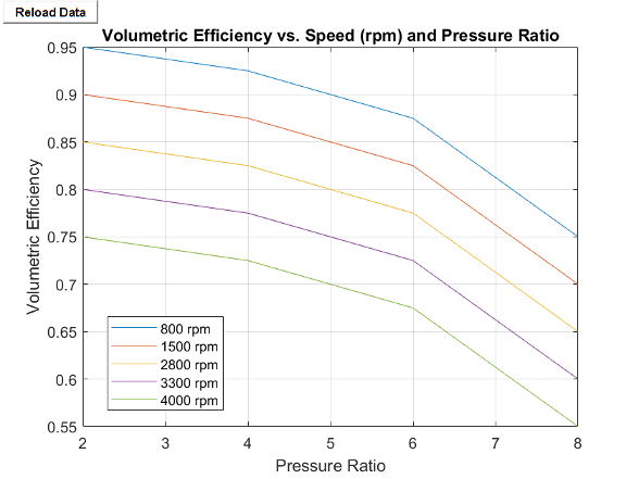
When you set Efficiency specification to
Tabulated, the block plots the compressor volumetric
efficiency against the pressure ratio for each element in the Shaft speed
vector, w parameter.
Assumptions and Limitations
The block may not be accurate for flow from port B to port A.
The block assumes that the flow is quasi-steady. The compressor does not accumulate mass.
The block is designed to operate in superheated vapor. The block may not be accurate in two-phase mixture or subcooled liquid.
Examples
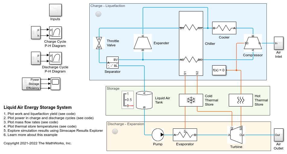
Liquid Air Energy Storage System
Models a grid-scale energy storage system based on cryogenic liquid air. When there is excess power, the system liquefies ambient air based on a variation of the Claude cycle. The cold liquid air is stored in a low-pressure insulated tank until needed. When there is high power demand, the system expands the stored liquid air to produce power based on the Rankine cycle.
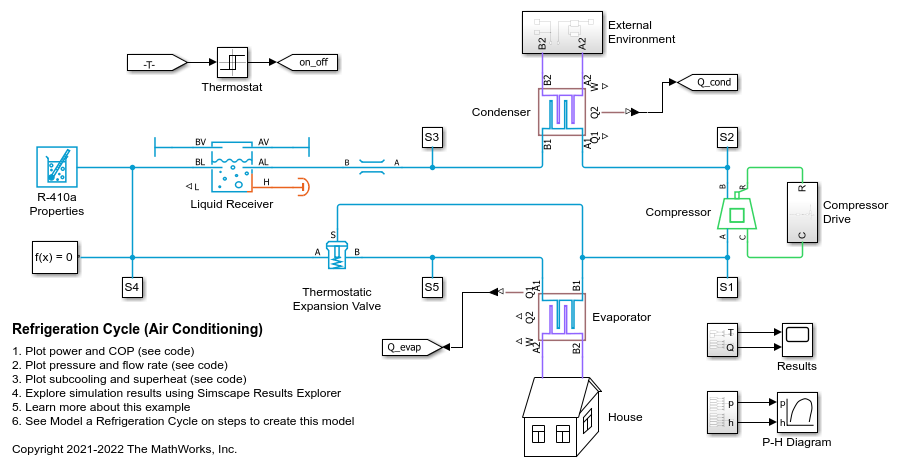
Refrigeration Cycle (Air Conditioning)
A refrigeration cycle for a home air conditioning system. See Model a Refrigeration Cycle for the recommended steps to build this model in the two-phase fluid domain.
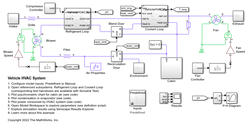
Vehicle HVAC System
Models the heating and cooling system of a passenger car. The cabin is represented as a volume of moist air exchanging heat with the external environment. The blower drives moist air through the evaporator, blend door, and heater core before returning to the cabin. The blend door controls the amount of air flow through the heater core. The recirculation door controls whether air is brought in from the external environment or from within the cabin.
Ports
Conserving
Parameters
References
[1] Mitchell, John W., and James E. Braun. Principles of Heating, Ventilation, and Air Conditioning in Buildings. Hoboken, NJ: Wiley, 2013.