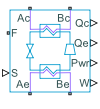
System-Level Refrigeration Cycle (2P)
System-level, two-phase refrigeration block in a gas, moist air, thermal liquid, or two-phase fluid network
Since R2023a
Libraries:
Simscape /
Fluids /
Two-Phase Fluid /
Thermodynamic Cycles
Description
The System-Level Refrigeration Cycle (2P) block models a basic refrigeration cycle consisting of a compressor, a condenser, a liquid receiver, a thermostatic expansion valve, and an evaporator. The block models the refrigerant loop within the block in the two-phase fluid domain using the fluid properties specified at port F. The condenser and evaporator external fluids can be part of a gas, moist air, thermal liquid, or two-phase fluid network. The external fluids are the fluids in the condenser and evaporator opposite the refrigerant.
When the compressor is on, the refrigeration cycle consumes power to transfer heat from the evaporator external fluid to the condenser external fluid. The subcomponents provide the specified nominal heat transfer under nominal operating conditions.
Block Structure
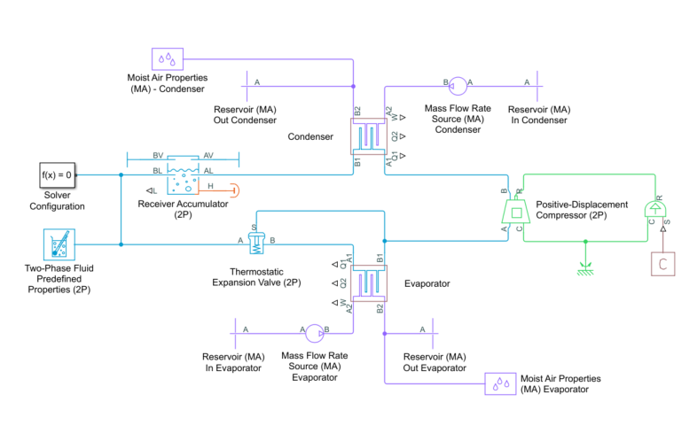
This block behaves as a simplified version of this refrigeration cycle made from Simscape™ Fluids™ blocks that model the condenser, compressor, evaporator, expansion device, and liquid receiver:

The refrigerant flows through the loop counterclockwise. The compressor, which is controlled by the signal at port S, sucks in refrigerant vapor and produces a hot, high-pressure vapor, which moves to the condenser. The condenser rejects heat from the refrigerant to the external fluid to condense the refrigerant. The liquid receiver acts as a storage tank for the refrigerant and only allows liquid flow to exit, which helps maintain normal operation even if fluctuating external conditions cause the condenser output to vary. From the tank, the refrigerant flows to the expansion device, which is typically a valve or capillary tube that produces a large pressure loss. The drop in pressure partially vaporizes the refrigerant, which chills it. The refrigerant moves to the evaporator, which absorbs heat from the external fluid to the cold refrigerant to vaporize the refrigerant.
The subcomponents of the System-Level Refrigeration Cycle (2P) block behave the same as these Simscape Fluids blocks in this model, but the equations for the positive displacement compressor, expansion valve, receiver component, and condenser and evaporator subcomponents vary. For more information on the individual components of a refrigeration system, see:
The compressor and evaporator components depend on the External fluid for condenser heat transfer and External fluid for evaporator heat transfer parameters. For more information, see:
The compressor subcomponent determines the refrigerant mass flow rate for the system. The
physical signal input port S controls the compressor
operation. When the value at port S is
0, the compressor is off and the mass flow rate is
0. When the value at port S is
1, the compressor runs at the nominal shaft speed, which
produces the nominal mass flow rate under nominal operating conditions. To
prevent reverse flow, the value of S must be greater than
or equal to 0.
The mass flow rate in the compressor is
where:
ηv is the volumetric efficiency.
S is the value of the signal at port S.
vin is the inlet specific volume.
is the nominal volumetric flow rate, which the block determines from the nominal mass flow rate, , which depends on the setting of the Capacity specification parameter:
When the Capacity specification parameter is
Cooling load,where Qcooling is the Nominal evaporator heat transfer parameter, h1 is the evaporator outlet specific enthalpy, and h4 is the valve outlet specific enthalpy.
When the Capacity specification parameter is
Heating load,where Qcooling is the Nominal condenser heat transfer parameter, h2 is the compressor outlet specific enthalpy, and h3 is the condenser outlet specific enthalpy.
When the Capacity specification parameter is
Refrigerant mass flow
											rate
, is the value of the Nominal mass flow rate parameter.
The fluid power that the compressor adds to the flow is
where:
hout,isem is the specific enthalpy evaluated at the output pressure for an isentropic process.
hin is the inlet specific enthalpy.
ηs is the isentropic efficiency.
When Performance specification is
Coefficient of performance for coolingorCoefficient of performance for heating, the block solves for ηs by calculating h2 and using the relationwhere h2isen is the compressor outlet specific enthalpy assuming an isentropic process.
When Performance specification is
Coefficient of performance for cooling, the block solves for h2 with where CoPcooling is the Coefficient of performance at nominal conditions parameter.When Performance specification is
Coefficient of
												performance for heating
, the block solves for h2 with where CoPheating is the Coefficient of performance at nominal conditions parameter.
When Performance specification is
Compressor isentropic
												efficiency
, ηs is the value of the Compressor isentropic efficiency parameter.
The block calculates the volumetric efficiency directly from the inlet and outlet specific volumes
where:
C is the clearance volume fraction that the block determines from the nominal operating conditions.
vin and vout are the inlet and outlet specific volumes evaluated at the inlet and outlet pressures.
The compressor subcomponent does not have mechanical rotational ports and does not need to calculate shaft torque. The mechanical power is
where ηm is the mechanical efficiency.
The relationship between mass flow rate, which the compressor determines, and the pressure drop across the thermostatic expansion valve subcomponent is
where:
vin is the inlet specific volume.
Δp is the pressure differential over the valve.
Δplam is the pressure threshold for transitional flow. Below this value, the flow is laminar.
The effective valve area depends on the pressure difference between the measured pressure, pbulb, and the equalization pressure, peq
where:
β is a valve constant the block determines from the nominal operating conditions.
Tevap is the evaporating temperature, which depends on the Pressure specification setting:
When Pressure specification is
Pressure at specified saturation
											temperature
, Tevap is the value of the Nominal evaporating (saturation) temperature parameter.When Pressure specification is
Specified pressure, Tevap is the saturation temperature that corresponds to the value of the Nominal evaporator pressure parameter.
ΔTstatic is the Static (minimum) evaporator superheat parameter.
psat(Tevap) is the fluid saturation pressure as a function of Tevap.
psat(Tevap+ΔTstatic) is the fluid saturation pressure as a function of Tevap+ΔTstatic.
pbulb is the fluid pressure of the bulb. This pressure is the saturation pressure at the evaporator outlet temperature.
peq is the equalization pressure, which is the evaporator pressure for this block.
The effective valve area has limits. The minimum effective valve area, Seff,min, is
where fleak is the value of the Ratio of leakage to nominal expansion valve opening parameter. The nominal effective valve area is
where:
Tcond is the condensing saturation temperature.
When Pressure specification is
Pressure at specified saturation
								temperature
, Tcond is the value of the Nominal condensing (saturation) temperature parameter.When Pressure specification is
Specified pressure, Tcond is the saturation temperature that corresponds to the value of the Nominal condenser pressure parameter.vcond is the liquid specific volume at Tcond.
The maximum effective valve area, Seff,mmax, is
where fmax is the value of the Ratio of maximum to nominal expansion valve opening parameter.
Excluding the receiver, the block assumes that the refrigerant mass flow rate is the same value through the loop. In the receiver, the total mass is based on the balance between the mass flow rate produced by the compressor and the mass flow rate metered by the expansion valve. The outflow from the receiver subcomponent is always liquid and perfectly insulated from the environment.
The liquid mass fraction in the receiver subcomponent is
where:
xliq is the liquid mass fraction.
liq,in is the portion of the flow in that is liquid.
out is the mass flow rate out of the receiver.
vaporization is the rate of vaporization from the liquid volume to the vapor volume.
condensation is the rate of condensation from the vapor volume to the liquid volume.
The pressure relates to the total mass via the specific volume using the relation
where:
V is the total receiver volume.
vliq is the is the specific volume of the liquid volume.
vvap is the is the specific volume of the vapor volume.
The condenser and evaporator subcomponents model the refrigerant thermal mass, but do not model fluid volume. For the condenser and evaporator, the energy conservation equation is
where:
M is the constant mass of refrigerant in the component.
hI is the refrigerant specific enthalpy at the component internal node.
is the refrigerant mass flow rate.
Q is the rate of heat transfer from the external fluid to the refrigerant.
hin and hout are the refrigerant specific enthalpy in and out of the component.
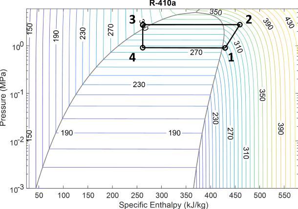
Visualize the P-H Diagram
To visualize the refrigeration cycle, use a Probe block from the Simscape > Utilities library to output the
variables p_cycle and h_cycle. These variables
contain the four pressure and specific enthalpy points of the refrigeration cycle.
Connect the variables to the P-H Diagram
(2P) block to visualize the refrigeration cycle.
This diagram shows the fluid attributes throughout the system for the refrigerant R-410a. Segment 1 to 2 is the compressor, segment 2 to 3 is the condenser, point 3 is the receiver, segment 3 to 4 is the expansion valve, and segment 4 to 1 is the evaporator.
Assumptions and Limitations
The block does not model reverse flow and limits the refrigeration cycle to zero and forward flow only. To prevent reverse flow, the block limits the compressor control to zero or forward operation and only models fluid volume in the liquid receiver subcomponent.
Excluding the liquid receiver, the subcomponents do not model refrigerant fluid volume, which prevents the accumulation of mass in subcomponents. As a result, the refrigerant mass flow rate is the same through the evaporator, compressor, and condenser subcomponents.
There is no refrigerant pressure loss in the evaporator or condenser.
The block does not model kinetic energy changes in the refrigerant flow.
The evaporator subcomponent models approximate pressure dynamics to maintain numerical robustness. However, the condenser subcomponent does not model approximate pressure dynamics, because the condenser pressure is equal to the receiver pressure, which does model pressure dynamics.
The condenser and evaporator subcomponents only model counter flow because the refrigerant is primarily in the two-phase mixture state within the condenser and evaporator. Consequently, the temperature is uniform across most of the condenser and evaporator, and there is no significant difference between counter flow and cross flow.
When determining the heat exchanger size, the block ignores the values of the Fraction of condensate entrained as water droplets parameters and assumes that the condensate is not entrained as droplets.
Examples
Model a Refrigeration Cycle
Model considerations for a closed-loop refrigeration cycle.
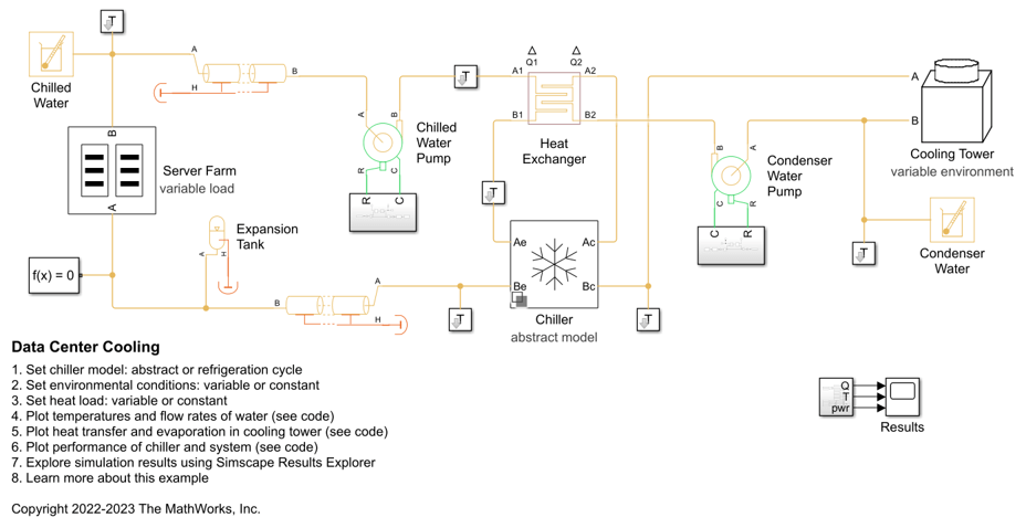
Data Center Cooling
Models the cooling system of a data center. The system consists of two separate water loops: a chilled water loop and a condenser water loop. The chilled water loop absorbs heat from the server farm and transfers it to the condenser water loop. The condenser water loop rejects this heat to the environment using a cooling tower.
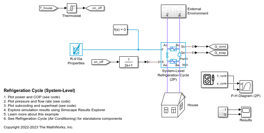
Refrigeration Cycle (System-Level)
Model a refrigeration cycle for a home air conditioning system at an abstract system level using the System-Level Refrigeration Cycle (2P) block. This block simplifies the set up of the refrigeration cycle by encapsulating the entire refrigerant loop in one block.
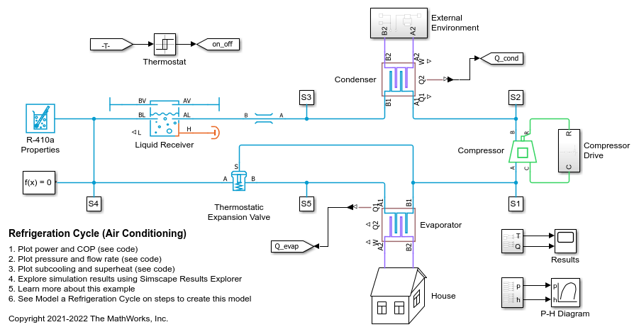
Refrigeration Cycle (Air Conditioning)
A refrigeration cycle for a home air conditioning system. See Model a Refrigeration Cycle for the recommended steps to build this model in the two-phase fluid domain.
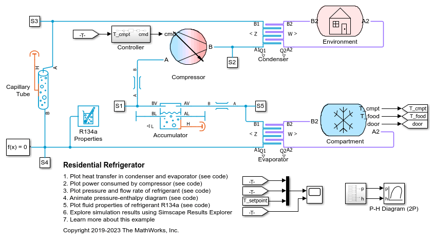
Residential Refrigerator
Models a basic refrigeration system that transfers heat between the refrigerant two-phase fluid and the environment moist air mixture. The compressor drives the R134a refrigerant through a condenser, a capillary tube, and an evaporator. An accumulator ensures that only vapor returns to the compressor.

Model an Ice Maker by Using Mode Charts in a Custom Simscape Block
Model an ice maker in Simscape™ by designing a custom block that uses mode charts to represent freezing water in the machine. You create a model that represents the refrigeration cycle and the ice compartment. Then, you create a custom Simscape block that uses a mode chart to model the states of the water, from liquid to solid. For more information about mode charts, see Mode Chart Modeling.