Generate HDL Code for Image Sharpening
This example shows how to use Vision HDL Toolbox™ to implement an FPGA-based module for image sharpening.
Vision HDL Toolbox provides image and video processing algorithms designed to generate readable, synthesizable code in VHDL® and Verilog® (with HDL Coder™). The generated HDL code when run on an FPGA (for example, AMD® XC7Z045) can process 1920x1080 full-resolution images at 60 frames per second.
This example shows how to use Vision HDL Toolbox to generate HDL code that sharpens a blurred image. Since Vision HDL Toolbox algorithms are available as MATLAB® System objects and Simulink® blocks, HDL code can be generated from MATLAB or Simulink. This example shows both workflows.
The workflow for an FPGA-targeted design is:
1. Create a behavioral model to represent design goals;
2. Replicate the design using algorithms, interfaces, and data types appropriate for FPGAs and supported for HDL code generation.
3. Simulate the two designs and compare the results to confirm that the HDL-optimized design meets the goals.
4. Generate HDL code from the design created in Step 2.
For Steps 2 and 3 in MATLAB, you must have MATLAB, Vision HDL Toolbox, and Fixed-Point Designer™. In Simulink, you need Simulink, Vision HDL Toolbox, and Fixed-Point Designer. In both cases, you must have HDL Coder to generate HDL code.
Behavioral Model
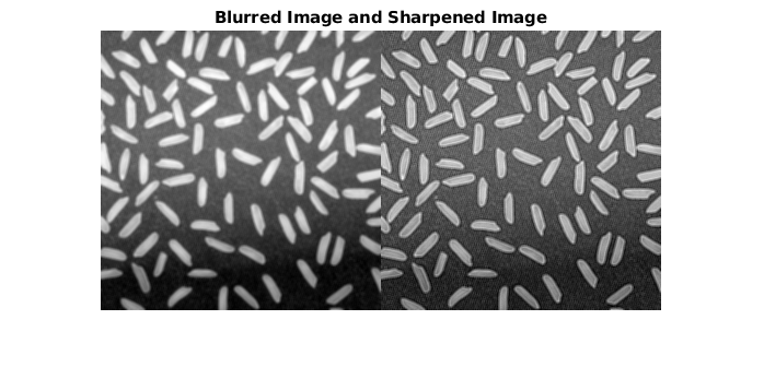
The input image imgBlur is shown on the left in the diagram below. On the right, the image is sharpened using the Image Processing Toolbox™ function imfilter.
Simulation time is printed as a bench mark for future comparison.
imgBlur = imread('riceblurred.png');
sharpCoeff = [0 0 0;0 1 0;0 0 0]-fspecial('laplacian',0.2);

f = @() imfilter(imgBlur,sharpCoeff,'symmetric');
fprintf('Elapsed time is %.6f seconds.\n',timeit(f));

imgSharp = imfilter(imgBlur,sharpCoeff,'symmetric');
figure
imshowpair(imgBlur,imgSharp,'montage')
title('Blurred Image and Sharpened Image')
Elapsed time is 0.000264 seconds.
HDL-Optimized Design Considerations
Three key changes need to be made to enable HDL code generation.
Use HDL-friendly algorithms: The functions in Image Processing Toolbox do not support HDL Code generation. Vision HDL Toolbox provides image and video processing algorithms designed for efficient HDL implementations. You can generate HDL code from these algorithms using Functions (Vision HDL Toolbox) and Blocks (Vision HDL Toolbox). Both workflows are provided in this example. To design an FPGA-based module, replace the functions from Image Processing Toolbox with their HDL-friendly counterparts from Vision HDL Toolbox. This example replaces
imfilterin the behavioral model with thevisionhdl.ImageFilterSystem object™ in MATLAB, or theImage Filterblock in Simulink.
Use streaming pixel interface: The functions from Image Processing Toolbox model at a high level of abstraction. They perform full-frame processing, operating on one image frame at a time. FPGA and ASIC implementations, however, perform pixel-stream processing, operating on one image pixel at a time. Vision HDL Toolbox blocks and System objects use a streaming pixel interface. Use
visionhdl.FrameToPixelsSystem object in MATLAB orFrame To Pixelsblock in Simulink to convert a full frame image or video to a pixel stream. The streaming pixel interface includes control signals that indicate each pixel's position in the frame. Algorithms that operate on a pixel neighborhood use internal memory to store a minimum number of lines. Vision HDL Toolbox provides the streaming pixel interface and automatic memory implementation to address common design issues when targeting FPGAs and ASICs. For more information on the streaming pixel protocol used by System objects from the Vision HDL Toolbox, see Streaming Pixel Interface (Vision HDL Toolbox).
Use fixed-point data representation: Functions from Image Processing Toolbox perform video processing algorithms in the floating-point or integer domain. The System objects and blocks from Vision HDL Toolbox require fixed-point data to generate HDL code to target FPGAs and ASICs. Converting a design to fixed-point can introduce quantization error. Therefore, the HDL-friendly model might generate an output slightly different from that obtained from the behavioral model. For most applications, small quantization errors within a tolerance are acceptable. You can tune the fixed-point settings to suit your requirements.
In this example, we use a static image as the source. This model is also able to process continuous video input.
Generate HDL Code from MATLAB
To generate HDL from MATLAB, your code needs to be divided into two files: test bench and design. The design file is used for implementing the algorithm in the FPGA or ASIC. The test bench file provides the input data to the design file and receives the design output.
Step 1: Create Design File
The function ImageSharpeningHDLDesign.m accepts a pixel stream and a control structure consisting of five control signals, and returns a modified pixel stream and control structure.
In this example, the design contains a System object visionhdl.ImageFilter. It is the HDL-friendly counterpart of the imfilter function. Configure it with the same coefficients and padding method as imfilter.
function [pixOut,ctrlOut] = ImageSharpeningHDLDesign(pixIn,ctrlIn)
% ImageSharpeningHDLDesign  Implement algorithms using pixel-stream
%       System objects from the Vision HDL Toolbox

%   Copyright 2015-2022 The MathWorks, Inc.

%#codegen
persistent sharpeningFilter;
if isempty(sharpeningFilter)
    sharpCoeff = [0 0 0;0 1 0;0 0 0]-fspecial('laplacian',0.2);
    sharpeningFilter = visionhdl.ImageFilter(...
    'Coefficients',sharpCoeff,...
    'PaddingMethod','Symmetric',...
    'CoefficientsDataType','Custom',...
    'CustomCoefficientsDataType',numerictype(1,16,12));
end

[pixOut,ctrlOut] = sharpeningFilter(pixIn,ctrlIn);
Step 2: Create Test Bench File
The test bench ImageSharpeningHDLTestBench.m reads in the blurred image. The frm2pix object converts the full image frame to a stream of pixels and control structures. The test bench calls the design function ImageSharpeningHDLDesign to process one pixel at a time. After the entire pixel-stream is processed, pix2frm converts the output pixel stream to a full-frame image. The test bench compares the output image to the reference output imgSharp.
...
[pixInVec,ctrlInVec] = frm2pix(imgBlur);
for p = 1:numPixPerFrm
    [pixOutVec(p),ctrlOutVec(p)] = ImageSharpeningHDLDesign(pixInVec(p),ctrlInVec(p));
end
imgOut = pix2frm(pixOutVec,ctrlOutVec);
% Compare the result
imgDiff = imabsdiff(imgSharp,imgOut);
fprintf('The maximum difference between corresponding pixels is %d.\n',max(imgDiff(:)));
fprintf('A total of %d pixels are different.\n',nnz(imgDiff));
...
Step 3: Simulate Design and Verify Result
Simulate the design with the test bench prior to HDL code generation to make sure there are no runtime errors.
ImageSharpeningHDLTestBench
The maximum difference between corresponding pixels is 1.
A total of 41976 pixels are different.

Simulation took 77.563316 seconds to finish.
The test bench displays the comparison result and the time spent on simulation. Due to quantization error and rounding error, out of a total of 256*256=65536 pixels, 38554 of imgOut are different from imgSharp. However, the maximum difference in intensity is 1. On a 0 to 255 scale, this difference is visually unnoticeable.
As we can see by comparing the simulation time in MATLAB with that of the behavioral model, the pixel-streaming protocol introduces significant overhead. You can use MATLAB Coder™ to speed up the pixel-streaming simulation in MATLAB. See Accelerate Pixel-Streaming Designs Using MATLAB Coder (Vision HDL Toolbox).
Step 4: Generate HDL Code
Once you are satisfied with the results of the FPGA-targeted model, you can use HDL Coder to generate HDL code from the design. You can run the generated HDL code in HDL simulators or load it into an FPGA and run it in a physical system.
Make sure that the design and test bench files are located in the same writable directory. To generate the HDL code, use the following command:
hdlcfg = coder.config('hdl');
hdlcfg.TestBenchName = 'ImageSharpeningHDLTestBench';
hdlcfg.TargetLanguage = 'Verilog';
hdlcfg.GenerateHDLTestBench = false;
codegen -config hdlcfg ImageSharpeningHDLDesign
For more detail on how to create and configure MATLAB to HDL projects, see the "Getting Started with MATLAB to HDL Workflow" tutorial in the HDL Coder documentation.
Generate HDL Code from Simulink
Step 1: Create HDL-Optimized Model
The ImageSharpeningHDLModel model is shown below.
modelname = 'ImageSharpeningHDLModel';
open_system(modelname);
set_param(modelname,'Open','on');
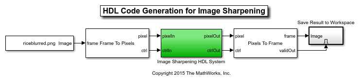
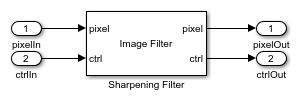
The model reads in the blurred image. The Frame To Pixels block converts a full-frame image to a pixel stream, and the Pixels To Frame block converts the pixel stream back to a full-frame image. The Image Sharpening HDL System contains an Image Filter block, which is the HDL-friendly counterpart in Vision HDL Toolbox of the imfilter function presented in the behavioral model.
set_param(modelname,'Open','off');
set_param([modelname '/Image Sharpening HDL System'],'Open','on');
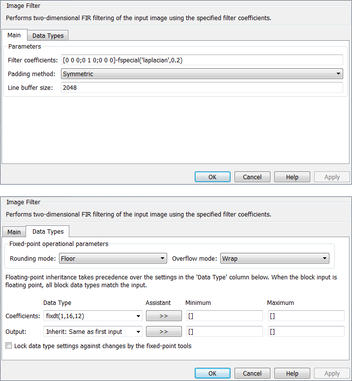
Configure the Image Filter block with the same sharpening coefficients and padding method as in the behavioral model, as shown on the masks below.
Step 2: Simulate Design and Verify Result
tic
sim(modelname);
toc
Elapsed time is 51.597866 seconds.
Simulink takes advantage of C code generation to speed up the simulation. Therefore, it is much faster than MATLAB simulation, although still slower than the behavioral model.
The simulation creates a new variable called imgOut in the workspace. Use the following commands to compare imgOut with imSharp generated from the behavioral model.
imgDiff = imabsdiff(imgSharp,imgOut);
fprintf('The maximum difference between corresponding pixels is %d.\n',max(imgDiff(:)));
fprintf('A total of %d pixels are different.\n',nnz(imgDiff));
The maximum difference between corresponding pixels is 1.
A total of 41976 pixels are different.
Due to quantization error and rounding error, out of a total of 256*256=65536 pixels, 41248 of imgOut are different from imgSharp. However, the maximum difference in intensity is 1. On a 0 to 255 scale, this difference is visually unnoticeable. (This reasoning is also presented in Step 3 in the "Generate HDL Code from MATLAB" Section.)
Step 3: Generate HDL Code
Once you are satisfied with the results of the FPGA-targeted model, you can use HDL Coder to generate HDL code from the design. You can run the generated HDL code in HDL simulators or load it into an FPGA and run it in a physical system.
Generate HDL code from the Image Sharpening HDL System using the following command:
makehdl('ImageSharpeningHDLModel/Image Sharpening HDL System')
set_param([modelname '/Image Sharpening HDL System'],'Open','off');
close_system(modelname,0);
close all;