imimposemin
Impose minima
Description
Examples
This example shows how to modify an image so that one area is always a regional minimum.
Read an image and display it. This image is called the mask image.
mask = imread('glass.png');
imshow(mask)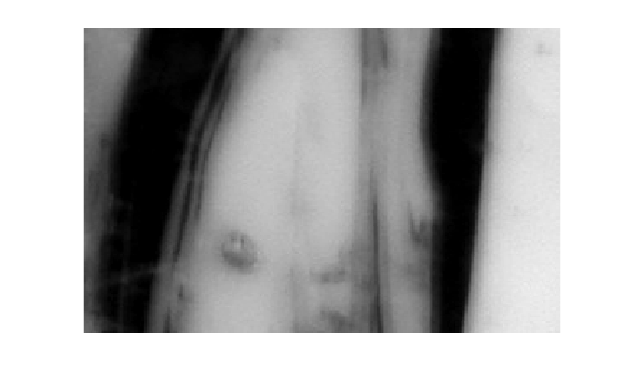
Create a binary image that is the same size as the mask image and sets a small area of the binary image to 1. These pixels define the location in the mask image where a regional minimum will be imposed. The resulting image is called the marker image.
marker = false(size(mask));
marker(65:70,65:70) = true;
Superimpose the marker over the mask to show where these pixels of interest fall on the original image. The small white square marks the spot. This code is not essential to the impose minima operation.
J = mask;
J(marker) = 255;
figure
imshow(J)
title('Marker Image Superimposed on Mask')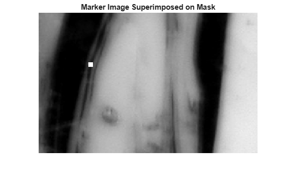
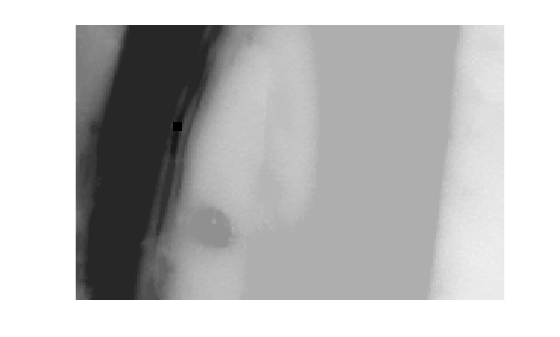
Impose the regional minimum on the input image using the imimposemin function. Note how all the dark areas of the original image, except the marked area, are lighter.
K = imimposemin(mask,marker);
figure
imshow(K)
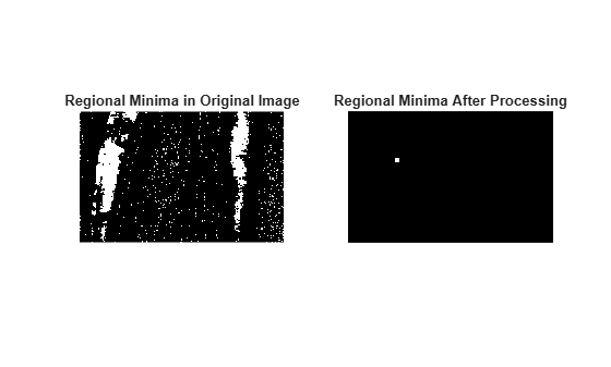
To illustrate how this operation removes all minima in the original image except the imposed minimum, compare the regional minima in the original image with the regional minimum in the processed image. These calls to imregionalmin return binary images that specify the locations of all the regional minima in both images.
BW = imregionalmin(mask);
figure
subplot(1,2,1)
imshow(BW)
title('Regional Minima in Original Image')

BW2 = imregionalmin(K);
subplot(1,2,2)
imshow(BW2)
title('Regional Minima After Processing')
Input Arguments
Grayscale mask image, specified as a numeric array of any dimension.
Data Types: single | double | int8 | int16 | int32 | int64 | uint8 | uint16 | uint32 | uint64
Binary marker image, specified as a numeric or logical array of the same size as the
grayscale mask image I.
Data Types: single | double | int8 | int16 | int32 | int64 | uint8 | uint16 | uint32 | uint64 | logical
Pixel connectivity, specified as one of the values in this table. The default
connectivity is 8 for 2-D images, and 26 for 3-D
images.
Value | Meaning | |
|---|---|---|
Two-Dimensional Connectivities | ||
| Pixels are connected if their edges touch. The neighborhood of a pixel are the adjacent pixels in the horizontal or vertical direction. |
Current pixel is shown in gray. |
| Pixels are connected if their edges or corners touch. The neighborhood of a pixel are the adjacent pixels in the horizontal, vertical, or diagonal direction. |
Current pixel is shown in gray. |
Three-Dimensional Connectivities | ||
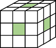
| Pixels are connected if their faces touch. The neighborhood of a pixel are the adjacent pixels in:
|
Current pixel is shown in gray. |
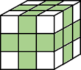
| Pixels are connected if their faces or edges touch. The neighborhood of a pixel are the adjacent pixels in:
|
Current pixel is center of cube. |
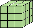
| Pixels are connected if their faces, edges, or corners touch. The neighborhood of a pixel are the adjacent pixels in:
|
Current pixel is center of cube. |


For higher dimensions, imimposemin uses the default value
conndef(ndims(I),"maximal")
Data Types: double | logical