Measure Eye Openings in Simulink
This example shows how to produce eye diagrams and related metrics for sampled data systems in Simulink®.
Set Up Eye Measurement Block
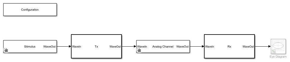
Open the model eyeMeasurementInDFECDRExampleModel attached with this example. The model was originally created in the SerDes Designer app and then exported to Simulink. For more information, see Design SerDes System and Export IBIS-AMI Model (SerDes Toolbox).
model = "eyeMeasurementInDFECDRExampleModel";
open_system(model);
In the eyeMeasurementInDFECDRExampleModel model, double-click on the Rx subsystem. Then right-click the DFECDR and select Look under mask to enter the DFECDR subsystem. Add an Eye Measurement block.
Note The Eye Measurement block is not supported for IBIS-AMI model generation. Remove the Eye Measurement block before exporting the model to IBIS-AMI.
Double-click on the Eye Measurement block to open its dialog.
Set the Configuration tab parameters to match the signal:
Set Enable threshold input port to
onSet Modulation to
ModulationSet Enable clock input port to
onSet Amplitude range to
[-0.2, 0.2]Set Hold off time to
IgnoreBitsand its unit toUISet Symbol time (s) to
SymbolTimeSet Sample time (s) to
SampleInterval
phaseOffset = 0.7;
Modulation, IgnoreBits, SymbolTime, and SampleInterval are model properties controlled by the Configuration block in the top level of the model.
In the Eye Mask tab:
Set Eye mask type to
RectangularSet W1 (UI) to
0.2Set H to
0.1
In the Metric Setup tab:
Set Store results in base workspace to
onSet Result variable name to
eyeResults
This saves the metrics to the base workspace in the variable named eyeResults once the simulation ends.
Apply the changes.
Connect Eye Measurement Block to DFECDR
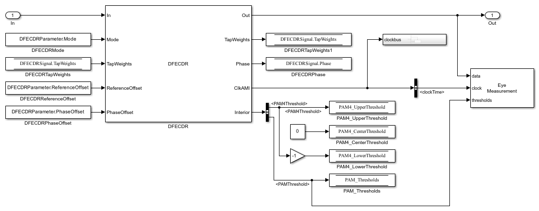
Connect the data input of the Eye Measurement block to the output signal from the DFECDR. Add a Bus Selector block. Connect the input of the bus selector to the ClkAMI output port on the DFECDR. Use the Bus Selector to select the signal clockTime from the bus.
Connect the output port from the bus selector to the clock input port on the Eye Measurement block. Connect the PAM_Thresholds signal from the DFECDR to the thresholds input to the Eye Measurement block.
open_system(model + "/Rx/DFECDR", "force");
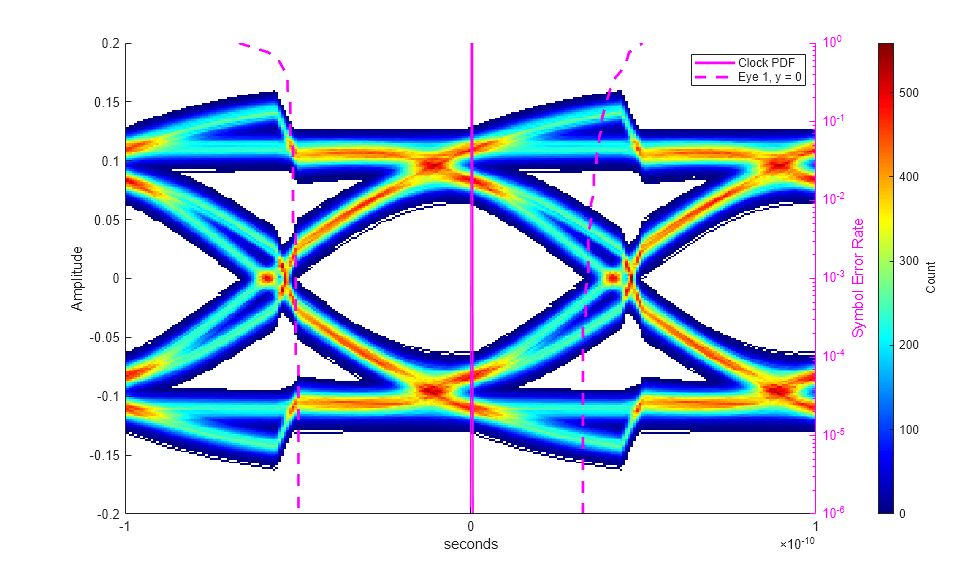
Run the simulation and confirm that the eye opening is centered, the correct number of unit intervals is visible, and that the dynamic range of the signal is fully within the diagram.
sim(model);
Export Metric Results
Once the simulation is complete, find the metric results in the base workspace.
disp(eyeResults);
         Metric          Position      Unit        SER     Extrapolation      Results
    _________________    ________    _________    _____    _____________    ____________

    "Eye Height"         {[  0]}     "Seconds"    1e-05       "None"        {1×1 struct}
    "Best Eye Height"    {[NaN]}     "NaN"        1e-05       "None"        {1×1 struct}
    "Eye Mask Margin"    {[NaN]}     "NaN"        1e-05       "none"        {1×1 struct}
To retrieve the width and height margins, select the last element in the results column of the table, and from that structure retrieve the field named Margin.
eyeResults.Results{end}.Margin
ans =

   -0.0035   -0.0176