Main Content

patternElevation

System object: phased.IsotropicAntennaElement
Namespace: phased

Plot isotropic antenna element directivity or pattern versus elevation

Syntax

patternElevation(sElem,FREQ)
patternElevation(sElem,FREQ,AZ)
patternElevation(sElem,FREQ,AZ,Name,Value)
PAT = patternElevation(___)

Description

patternElevation(sElem,FREQ) plots the 2-D element directivity pattern versus elevation (in dBi) for the element sElem at zero degrees azimuth angle. The argument FREQ specifies the operating frequency.

patternElevation(sElem,FREQ,AZ), in addition, plots the 2-D element directivity pattern versus elevation (in dBi) at the azimuth angle specified by AZ. When AZ is a vector, multiple overlaid plots are created.

patternElevation(sElem,FREQ,AZ,Name,Value) plots the element pattern with additional options specified by one or more Name,Value pair arguments.

PAT = patternElevation(___) returns the element pattern. PAT is a matrix whose entries represent the pattern at corresponding sampling points specified by the 'Elevation' parameter and the AZ input argument.

Input Arguments

expand all

Isotropic antenna element, specified as a phased.IsotropicAntennaElement System object.

Example: sElem = phased.IsotropicAntennaElement;

Frequency for computing directivity and pattern, specified as a positive scalar. Frequency units are in hertz.

  • For an antenna or microphone element, FREQ must lie within the range of values specified by the FrequencyRange or the FrequencyVector property of the element. Otherwise, the element produces no response and the directivity is returned as –Inf. Most elements use the FrequencyRange property except for phased.CustomAntennaElement and phased.CustomMicrophoneElement, which use the FrequencyVector property.

  • For an array of elements, FREQ must lie within the frequency range of the elements that make up the array. Otherwise, the array produces no response and the directivity is returned as –Inf.

Example: 1e8

Data Types: double

Azimuth angles for computing sensor or array directivities and patterns, specified as a 1-by-N real-valued row vector where N is the number of desired azimuth directions. Angle units are in degrees. The azimuth angle must lie between –180° and 180°.

The azimuth angle is the angle between the x-axis and the projection of the direction vector onto the xy plane. This angle is positive when measured from the x-axis toward the y-axis.

Example: [0,10,20]

Data Types: double

Name-Value Arguments

Specify optional pairs of arguments as Name1=Value1,...,NameN=ValueN, where Name is the argument name and Value is the corresponding value. Name-value arguments must appear after other arguments, but the order of the pairs does not matter.

Before R2021a, use commas to separate each name and value, and enclose Name in quotes.

Displayed pattern type, specified as the comma-separated pair consisting of 'Type' and one of

  • 'directivity' — directivity pattern measured in dBi.

  • 'efield' — field pattern of the sensor or array. For acoustic sensors, the displayed pattern is for the scalar sound field.

  • 'power' — power pattern of the sensor or array defined as the square of the field pattern.

  • 'powerdb' — power pattern converted to dB.

Example: 'powerdb'

Data Types: char

Elevation angles, specified as the comma-separated pair consisting of 'Elevation' and a 1-by-P real-valued row vector. Elevation angles define where the array pattern is calculated.

Example: 'Elevation',[-90:2:90]

Data Types: double

Output Arguments

expand all

Element directivity or pattern, returned as an P-by-N real-valued matrix. The dimension P is the number of elevation angles determined by the 'Elevation' name-value pair argument. The dimension N is the number of azimuth angles determined by the AZ argument.

Examples

expand all

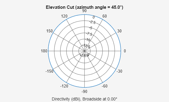
Plot an elevation cut of directivity of an isotropic antenna element at 45 degrees azimuth for all elevation angles and at 45 degrees for a span of elevation angles. Assume the operating frequency is 500 MHz.

Create the antenna element.

fc = 500e6;
antenna = phased.IsotropicAntennaElement('FrequencyRange',[100,900]*1e6);

Plot the directivity for all elevation angles.

patternElevation(antenna,fc,45)

Plot the directivity for a span of elevation angles using the Elevation parameter.

patternElevation(antenna,fc,45,'Elevation',[-20:20])
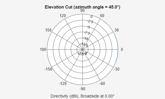
More About

expand all

Version History

Introduced in R2015a