step
System object: phased.SubbandMVDRBeamformer
Namespace: phased
Wideband MVDR beamforming
Syntax
Y = step(sMVDR,X)

Y = step(sMVDR,X,XT)

Y = step(sMVDR,X,ang)

[Y,Wts]
= step(sMVDR,___)

[Y,Freq] = step(sMVDR,___)

[Y,Wts,Freq]
= step(sMVDR,X,XT,ang)
Description
Note
Starting in R2016b, instead of using the step method
to perform the operation defined by the System object™, you can
call the object with arguments, as if it were a function. For example, y
= step(obj,x) and y = obj(x) perform
equivalent operations.
Y = step(sMVDR,X)X, and
returns the beamformed output in Y. This syntax
uses X for training samples to calculate the
beamforming weights. Use the Direction property
to specify the beamforming direction.
Y = step(sMVDR,X,XT)XT as
the training samples to calculate the beamforming weights. This syntax
applies only when you set the TrainingInputPort property
to true. Use the Direction property
to specify the beamforming direction.
Y = step(sMVDR,X,ang)ang as
the beamforming direction. This syntax applies only when you set the DirectionSource property
to 'Input port'.
[ returns
the beamforming weights, Y,Wts]
= step(sMVDR,___)Wts, when you set the WeightsOutputPort property
to true.
[Y,Freq] = step( returns
the center frequencies of the subbands, sMVDR,___)Freq,
when you set the SubbandsOutputPort property
to true. Freq is a length-K column
vector where, K is the number of subbands specified
in the NumSubbands property.
You can combine optional input arguments when you set their
enabling properties. Optional input arguments must be listed in the
same order as their enabling properties. For example, [Y,Wts,Freq]
= step(sMVDR,X,XT,ang) is valid when you specify TrainingInputPort to true and
specify DirectionSource to 'Input port'.
Note
The object performs an initialization the first time the object is executed. This
initialization locks nontunable properties
and input specifications, such as dimensions, complexity, and data type of the input data.
If you change a nontunable property or an input specification, the System object issues an error. To change nontunable properties or inputs, you must first
call the release method to unlock the object.
Input Arguments
Output Arguments
Examples
Apply subband MVDR beamforming to an underwater acoustic 11-element ULA. The incident angle of the signal is azimuth and elevation. The signal is an FM chirp having a bandwidth of 1 kHz. The speed of sound is 1500 m/s.
Simulate signal
array = phased.ULA('NumElements',11,'ElementSpacing',0.3);
fs = 2e3;
carrierFreq = 2000;
t = (0:1/fs:2)';
sig = chirp(t,0,2,fs/2);
c = 1500;
collector = phased.WidebandCollector('Sensor',array,'PropagationSpeed',c,...
    'SampleRate',fs,'ModulatedInput',true,...
    'CarrierFrequency',carrierFreq);
incidentAngle = [10;0];
sig1 = collector(sig,incidentAngle);
noise = 0.3*(randn(size(sig1)) + 1j*randn(size(sig1)));
rx = sig1 + noise;
Apply MVDR beamforming
beamformer = phased.SubbandMVDRBeamformer('SensorArray',array,...
    'Direction',incidentAngle,'OperatingFrequency',carrierFreq,...
    'PropagationSpeed',c,'SampleRate',fs,'TrainingInputPort',true, ...
    'SubbandsOutputPort',true,'WeightsOutputPort',true);
[y,w,subbandfreq] = beamformer(rx, noise);
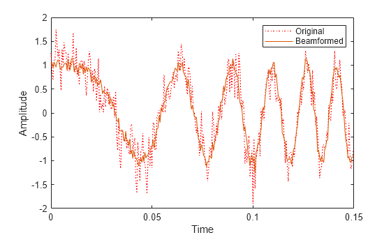
Plot the signal that is input to the middle sensor (channel 6) vs the beamformer output.
plot(t(1:300),real(rx(1:300,6)),'r:',t(1:300),real(y(1:300)))
xlabel('Time')
ylabel('Amplitude')
legend('Original','Beamformed');
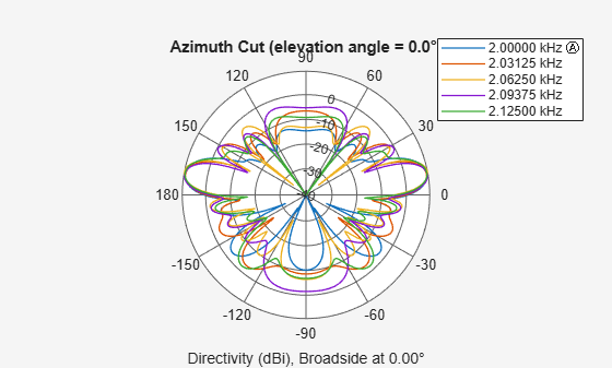
Plot array response
Plot the response pattern for five bands
pattern(array,subbandfreq(1:5).',-180:180,0,...
    'PropagationSpeed',c,'Weights',w(:,1:5));
Apply subband MVDR beamforming to an underwater acoustic 11-element ULA. Beamform the arriving signals to optimize the gain of a linear FM chirp signal arriving from 0 degrees azimuth and 0 degrees elevation. The signal has a bandwidth of 2.0 kHz. In addition, there unit amplitude 2.250 kHz interfering sine wave arriving from 28 degrees azimuth and 0 degrees elevation. Show how the MVDR beamformer nulls the interfering signal. Display the array pattern for several frequencies in the neighborhood of 2.250 kHz. The speed of sound is 1500 meters/sec.
Simulate Arriving Signal and Noise
array = phased.ULA('NumElements',11,'ElementSpacing',0.3);
fs = 2000;
carrierFreq = 2000;
t = (0:1/fs:2)';
sig = chirp(t,0,2,fs/2);
c = 1500;
collector = phased.WidebandCollector('Sensor',array,'PropagationSpeed',c,...
    'SampleRate',fs,'ModulatedInput',true,...
    'CarrierFrequency',carrierFreq);
incidentAngle = [0;0];
sig1 = collector(sig,incidentAngle);
noise = 0.3*(randn(size(sig1)) + 1j*randn(size(sig1)));
Simulate Interfering Signal
Combine both the desired and interfering signals.
fint = 250;
sigint = sin(2*pi*fint*t);
interfangle = [28;0];
sigint1 = collector(sigint,interfangle);
rx = sig1 + sigint1 + noise;
Apply MVDR Beamforming
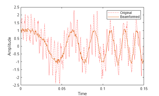
Use the combined noise and interfering signal as training data.
beamformer = phased.SubbandMVDRBeamformer('SensorArray',array,...
    'Direction',incidentAngle,'OperatingFrequency',carrierFreq,...
    'PropagationSpeed',c,'SampleRate',fs,'TrainingInputPort',true,...
    'NumSubbands',64,...
    'SubbandsOutputPort',true,'WeightsOutputPort',true);
[y,w,subbandfreq] = beamformer(rx,sigint1 + noise);
tidx = [1:300];
plot(t(tidx),real(rx(tidx,6)),'r:',t(tidx),real(y(tidx)))
xlabel('Time')
ylabel('Amplitude')
legend('Original','Beamformed')
Plot Array Response Showing Beampattern Null
Plot the response pattern for five bands near 2.250 kHz.
fdx = [5,7,9,11,13];
pattern(array,subbandfreq(fdx).',-50:50,0,...
    'PropagationSpeed',c,'Weights',w(:,fdx),...
    'CoordinateSystem','rectangular');
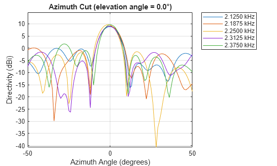
The beamformer places a null at 28 degrees for the subband containing 2.250 kHz.
References
[1] Proakis, J. Digital Communications. New York: McGraw-Hill, 2001.
[2] Skolnik, M. Introduction to Radar Systems, 3rd Ed. New York: McGraw-Hill
[3] Saakian, A. Radio Wave Propagation Fundamentals. Norwood, MA: Artech House, 2011.
[4] Balanis, C. Advanced Engineering Electromagnetics. New York: Wiley & Sons, 1989.
[5] Rappaport, T. Wireless Communications: Principles and Practice, 2nd Ed New York: Prentice Hall, 2002.
Version History
Introduced in R2015b