FEM-Parameterized PMSM
Permanent magnet synchronous motor defined in terms of magnetic flux linkage

Libraries:
Simscape /
Electrical /
Electromechanical /
Permanent Magnet
Description
The FEM-Parameterized PMSM block models a permanent magnet synchronous motor (PMSM) defined in terms of magnetic flux linkage. Use this block to model any three-phase motor that has a permanent magnet rotor such as:
Axial flux (pancake) motors
Brushless servomotors
Motors with interior magnet rotors, such as an interior permanent magnet (IPM) motor or an interior permanent magnet synchronous motors (IPMSMs)
Motors with surface-mounted magnet rotors:
Surface permanent magnet (SPM) motors or surface permanent magnet synchronous motors (SPMSMs)
Brushless direct current (BLDC) motors
You parameterize the block by using tabulated data of the motor magnetic flux as a function of current and rotor angle. This is the way that finite element method (FEM) packages usually export flux information. Because the block uses tabulated data, the flux can vary nonlinearly with both rotor angle and current. The nonlinear dependence on rotor angle enables the block to support trapezoidal flux profiles exhibited by BLDC motors and also capture the higher harmonics for motors with only approximately sinusoidal flux profiles.
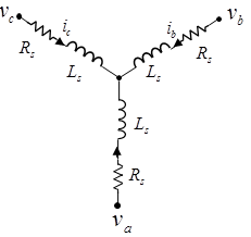
This figure shows the equivalent circuit for a wye-connected PMSM.
This figure shows the motor construction with a single pole-pair on the rotor. The rotor angle is zero when the permanent magnet flux aligns with the A-phase magnetic axis.
In practice, the flux linking each of the three windings depends on all three currents and the rotor angle. Tabulating the flux as a function of four independent variables can lead to simulation inefficiency and significant memory requirements. The block, therefore, lets you use the Modeling option parameter to specify how to model the flux and torque:
2-D partial derivative data — 2-D table lookup, with options to tabulate in terms of current and the rotor angle, or in terms of
d-axis andq-axis currents. The first option assumes constant mutual inductance and supports nonsinusoidal back electromotive force (EMF) profiles. The second option assumes a sinusoidal back EMF and captures saturation effects for IPMSMs.3-D partial derivative data — 3-D table lookup, based on direct current, quadrature current, and the rotor angle. You provide the flux lookup data for the a phase. The block uses Park transform to map the three stator winding currents to direct and quadrature currents. This method reduces the data complexity compared to the 4-D table lookup and results in improved simulation performance.
4-D partial derivative data — 4-D table lookup, based on the three stator winding currents and the rotor angle. You provide the flux lookup data for the a phase. This model has higher fidelity than the 2-D and 3-D partial derivative data models, but it has the most inefficient simulation performance and the highest memory requirements.
3-D flux linkage data — 3-D table lookup, based on the flux linkage data. You can provide the flux linkage data in a variety of formats. The block uses Park transform to map the three stator winding currents to direct and quadrature currents. This method reduces the data complexity compared to the 4-D table lookup and results in improved simulation performance.
Some of the Modeling option parameter settings also enable thermal ports. For more information, see Model Thermal Effects.
By default, the block implements a wye-wound configuration for the stator windings for all these parameterization methods. However, you can switch to a delta-wound or an open-end configuration by using the Winding type parameter. In the delta-wound configuration, the a-phase connects ports a and b, the b-phase between ports b and c and the c-phase connects ports c and a.
Note
Simscape™ Electrical™ includes several blocks that can model the same type of motor or actuator. Choose a block that has sufficient modeling detail for the engineering design questions that you need to answer. Do not use a block that has more modeling detail than you need, because higher-fidelity models slow down simulation and are more complex to parameterize.
Blocks like the FEM-Parameterized PMSM block define motor behavior in terms of flux linkage. These models have a high level of fidelity. Use this block only when you need a high level of modeling detail, for example, to predict efficiency for traction applications or to capture torque and electrical current harmonics. For more information about choosing the right block to model your motor at the right level of fidelity, see Choose Blocks to Model Motors or Actuators.
2-D Data Model with Constant Mutual Inductance
In this 2-D flux data model, the flux linking each winding is assumed to depend nonlinearly only on the current in that same winding, plus the rotor angle. In practice, this is a reasonable assumption for many permanent magnet synchronous motors; however, it is less accurate for switched reluctance motors. Given this assumption, the fluxes in the three windings are:
where is the flux linkage for the A-phase winding as a function of the
rotor angle and A-phase current. Θr = 0 corresponds to the rotor d-axis
aligning with the A-phase positive magnetic flux direction.
Ms is the stator-stator mutual
inductance.
For improved numerical performance, the equations implemented in the block actually work with the partial derivatives of flux linkage with respect to current, , and the rotor angle, , rather than the flux directly. If your FEM package does not export these partial derivatives, you can determine them using a MATLAB® script. See the Solenoid Parameterized with FEM Data example model and its supporting MATLAB script for an example of how to do this.
The electrical equations for the block, defined in terms of flux partial derivatives, are:
where
va, vb, vc are the voltages applied to the A, B, and C stator windings.
ia, ib, ic are the stator currents in each of the three windings.
Rs is the resistance of each of the stator windings.
Ms is the stator-stator mutual inductance.
are the partial derivatives of flux linkage with respect to stator current in each of the three windings.
is the partial derivative of flux linkage with respect to the rotor angle.
The block can automatically calculate the torque matrix from the flux information
that you provide. Alternatively, you can set the Calculate torque
matrix? parameter to No and directly
specify the torque as a function of current and the rotor angle. See the FEM-Parameterized Rotary Actuator block reference page for more
information.
2-D Data Model with Sinusoidal Back EMF
In this 2-D flux data model, the flux linking each winding is assumed to depend nonlinearly on all stator winding currents, plus it is assumed that the permanent magnet flux linkage is sinusoidal. Interior magnet PMSMs (or IPMSMs) usually fit this assumption well. The equations are:
where
id and iq are the
d-axis andq-axis currents, respectively.ϕd and ϕq are the
d-axis andq-axis flux linkages, respectively.ϕm is the permanent magnet flux linkage.
Ld and Lq are the
d-axis andq-axis inductances, respectively. They are assumed to depend on thed-axis andq-axis currents.N is the number of pole pairs.
T is the electrical torque.
3-D Partial Derivative Data Model Using Park Transform
Working with four-dimensional data has both a simulation performance cost and a memory cost. To reduce the table dimension to three-dimensional, the 3-D data model uses Park transform to map the three currents to direct and quadrature currents:
In the general case, Park transform maps to direct, quadrature, and zero-sequence currents. However, the zero-sequence current is typically small under normal operating conditions. Therefore, the model neglects the dependence of the flux linkage terms on zero-sequence current, and determines the flux linkage in terms of just direct and quadrature currents plus the rotor angle. The flux equation for the 3-D data model is:
The electrical equations for the block are also defined in terms of flux partial
derivatives, similar to the 4-D data model. You can calculate 3-D flux linkage
partial derivative data from 4-D flux linkage data using ee_calculateFluxPartialDerivatives.
4-D Partial Derivative Data Model
The flux linking each of the windings is a function of the current in that winding, the currents in the other two windings, and the rotor angle. For full accuracy, the 4-D flux data model assumes that the flux linkage is a function of the three currents and the rotor angle, therefore performing four-dimensional table lookups. The flux equation is:
where
ϕa, ϕb, ϕc are the flux linkages for the A, B, and C stator windings.
ia, ib, ic are the stator currents in each of the three windings.
Θr is the rotor angle. Θr = 0 corresponds to the case where the permanent magnet flux is aligned with the A-phase stator winding flux.
N is the number of pole pairs.
Flux linkage data is assumed cyclic with Θr. If, for example, the motor has six pole pairs, then the range for the data is 0 ≤ Θr ≤ 60°. You must provide data both at 0 and 60 degrees, and because the data is cyclic, the flux linkage partial derivatives must be the same at these two end points.
The torque equation is:
The 4-D data model does not have an option for the block to determine torque from flux linkage. Because of the increased numerical overhead in the 4-D case, it is better to precalculate the torque just once, rather than calculate it every time you run the simulation.
For improved numerical performance, the equations implemented in the block
actually work with the partial derivatives of flux linkage with respect to the three
currents and the rotor angle, rather than the flux directly. If your FEM package
does not export these partial derivatives, you can determine them using ee_calculateFluxPartialDerivatives.
The electrical equations for the block, defined in terms of flux partial derivatives, are:
where
va, vb, vc are the voltages applied to the A, B, and C stator windings.
ia, ib, ic are the stator currents in each of the three windings.
Rs is the resistance of each of the stator windings.
3-D Flux Linkage Data Models
The 3-D flux linkage data options let you work with raw flux linkage data exported from your finite-element (FE) motor design tool. This is in contrast to the 3-D partial derivative data options, for which you need to determine the partial derivatives. You can provide flux linkage data in a variety of formats, to support different FE tool conventions:
Tabulate DQ-axes flux linkage data or A-phase flux linkage data — Some tools support working with flux linkage resolved into direct (D) and quadrature (Q) axes. An advantage of this approach is that data for rotor angles in the range 0 to 360/N/3 degrees is required (where N is the number of pole pairs). Other tools work directly with A-, B-, and C-phase flux linkages, and for this you can import just the A-phase flux linkage, for which the rotor angle range must be in the range 0 to 360/N degrees. The implicit assumption of importing just the A-phase data is that the B and C phase data is the same except shifted in phase.
Tabulate using Cartesian or polar current coordinates — Cartesian tabulation implies the flux linkage is tabulated in terms of D-axis current and Q-axis current (plus the rotor angle). Alternatively, polar tabulation involves tabulating flux linkages in terms of current magnitude, current advance angle relative to the Q-axis, and the rotor angle. The advantage of polar coordinates is that it more naturally reflects the permitted operating currents, thereby avoiding unused table data points.
These conventions result in four Flux linkage data format parameterization options:
D and Q axes flux linkages as a function of D-axis current
                            (iD), Q-axis current (iQ), and rotor angle (theta)
D and Q axes flux linkages as a function of peak current magnitude (I), current advance angle (B), and rotor angle (theta)A-phase flux linkage as a function of D-axis current (iD), Q-axis current (iQ), and rotor angle (theta)A-phase flux linkage as a function of peak current magnitude (I), current advance angle (B), and rotor angle (theta)
The FEM-Parameterized PMSM block requires 3-D flux linkage data. To convert 2-D flux linkage
data, F(id,iq), into a 3-D table, F(id,iq,x),
use the repmat function.
Besides selecting the flux linkage data format used by your FE tool, you have to select the version of Park transform used by the tool. The four conventions are described below and correspond to the four options for the Park’s convention for tabulated data drop-down menu.
Note
When looking at logged values for D- and Q-axis currents, keep in mind that for each of these options, the format is converted, as needed, so that internally the FEM-Parameterized PMSM block consistently uses Option 1.
Note
To preserve higher-order harmonics due to the permanent magnet back EMF,
provide the A-phase flux data rather than the D-axis and Q-axis flux data.
Conversely, if you provide D-axis and Q-axis fluxes, the Park's transform
removes the higher-order harmonics. Working with D and Q fluxes is sufficient
for many applications, particularly if you set the Winding
type parameter to Wye-wound and there
aren't connections to the neutral port of this block. For this particular case,
the constraint that the sum of the currents is zero at the neutral port removes
all third-order harmonics.
This is the Park’s convention used internally by Simscape Electrical motor and machine blocks. All other options are converted into this format.

N: number of pole pairs
θr: rotor angle
id, iq: D-axis and Q-axis currents
ip: Current magnitude =
β: Current advance angle =
Corresponding Park transform is
where ia, ib, and ic are the A-phase, B-phase, and C-phase currents, respectively.

N: number of pole pairs
θr: rotor angle
id, iq: D-axis and Q-axis currents
ip: Current magnitude =
β: Current advance angle =
Corresponding Park transform is
where ia, ib, and ic are the A-phase, B-phase, and C-phase currents, respectively.

N: number of pole pairs
θr: rotor angle
id, iq: D-axis and Q-axis currents
ip: Current magnitude =
β: Current advance angle =
Corresponding Park transform is
where ia, ib, and ic are the A-phase, B-phase, and C-phase currents, respectively.

N: number of pole pairs
θr: rotor angle
id, iq: D-axis and Q-axis currents
ip: Current magnitude =
β: Current advance angle =
Corresponding Park transform is
where ia, ib, and ic are the A-phase, B-phase, and C-phase currents, respectively.
Calculate Total Losses
The FEM-Parameterized PMSM block models ohmic losses, mechanical losses, and iron losses.
The sum of these losses defines the total losses in the system, as described in this equation:
where Pohmic represents the ohmic losses, Pmech represents the mechanical losses, and Piron represents the iron losses.
Calculate Ohmic Losses
Ohmic losses, or copper losses, represent the energy losses associated with the passage of the current through the resistances of the stator windings. The block calculates the ohmic losses using this equation:
where ia, ib, and ic are the A-phase, B-phase, and C-phase currents, and Ra, Rb, and Rc are the temperature-adjusted resistances at each phase.
If you expose the thermal port of the block, these resistances linearly increase with the temperature. For more information, see Temperature Dependency for Stator Resistance.
Calculate Mechanical Losses
Mechanical losses represent the energy losses associated with the physical movement of the motor components. To model mechanical losses, set the Rotor damping parameter to a nonzero value. The block calculates the mechanical losses using this equation:
where B is the value of the Rotor damping parameter and ω is the rotor angular velocity.
Calculate Iron Losses
The FEM-Parameterized PMSM block models iron losses according to the parameterization methods you choose for flux and torque.
These iron losses produce heat. The block injects the heat from rotor iron losses into the HR thermal port that represents the rotor thermal mass. The block splits the stator iron losses in three equal parts and injects each part into the stator winding thermal ports, HA, HB, and HC.
For the 2-D partial derivative data, 3-D partial derivative data, and 4-D partial derivative data options, with or without thermal ports, the iron loss model is based on the work of Mellor [1]. Iron losses are divided into two terms, one representing the main magnetizing path, and the other representing the cross-tooth tip path that becomes active during field weakened operation.
The term representing the main magnetizing path depends on the induced RMS stator voltage, :
This is the dominant term during no-load operation. k is the back EMF constant relating RMS volts per Hz. It is defined as , where f is the electrical frequency. The first term on the right-hand side is the magnetic hysteresis loss, the second is the eddy current loss and the third is the excess loss. The three coefficients appearing on the numerators are derived from the values that you provide for the open-circuit hysteresis, eddy, and excess losses.
The term representing the cross-tooth tip path becomes important when a demagnetizing field is set up and can be determined from a finite element analysis short-circuit test. It depends on the RMS EMF associated with the cross-tooth tip flux, :
The three numerator terms are derived from the values you provide for the short-circuit hysteresis, eddy, and excess losses.
For the 3-D flux linkage data with or without thermal ports, you can also model the iron losses based on the Steinmetz equation. The Steinmetz method scales for different motor speeds or electrical frequencies so that iron loss data is only required as function of motor currents.
If, in the Iron Losses setting, you set the
Model parameter to Specify open and short
circuit loss data (permanent magnet motors only), the block
uses the Steinmetz method, but assumes constant coefficients and no dependency
on peak current and current phase advance. Select this option if you have dyno
measurements or if you perform an FE analysis to get the iron losses from just
open-circuit and short-circuit simulations.
Conversely, if you set the Flux linkage data format
parameter to either D and Q axes flux linkages as a function of
peak current magnitude (I), current advance angle (B), and rotor angle
(theta) or A-phase flux linkage as a function of
peak current magnitude (I), current advance angle (B), and rotor angle
(theta) , then the block tabulated the coefficients with the
Peak current magnitude vector, I and Current
advance angle vector, B parameters, so that the iron losses are
given by:
where:
f is the electrical instantaneous frequency, in
Hz, and is equal to the rotor mechanical speed multiplied by the number of pole pairs. This frequency is a variable that changes over time.khr(Ip,β) is the Rotor hysteresis loss coefficient, k_hr(I,B).
kJr(Ip,β) is the Rotor eddy current loss coefficient, k_Jr(I,B).
ker(Ip,β) is the Rotor excess current loss coefficient, k_er(I,B).
khs(Ip,β) is the Stator hysteresis loss coefficient, k_hs(I,B).
kJs(Ip,β) is the Stator eddy current loss coefficient, k_Js(I,B).
kes(Ip,β) is the Stator excess current loss coefficient, k_es(I,B).
Similarly, if you set the Flux linkage data format
parameter to either D and Q axes flux linkages as a function of
D-axis current (iD), Q-axis current (iQ), and rotor angle
(theta) or A-phase flux linkage as a function of
D-axis current (iD), Q-axis current (iQ), and rotor angle
(theta), then the iron losses are given by:
where:
khr(id,iq) is the Rotor hysteresis loss coefficient, k_hr(id,iq).
kJr(id,iq) is the Rotor eddy current loss coefficient, k_Jr(id,iq).
ker(id,idq) is the Rotor excess current loss coefficient, k_er(id,iq).
khs(id,iq) is the Stator hysteresis loss coefficient, k_hs(id,iq).
kJs(id,iq) is the Stator eddy current loss coefficient, k_Js(id,iq).
kes(id,iq) is the Stator excess current loss coefficient, k_es(id,iq).
Select this option only in conjunction with a motor design tool that can calculate the coefficients. You can export the Steinmetz coefficients lookup tables in Cartesian coordinates (id,iq) or radial coordinates (Ip,β) by using FEM tools such as Motor-CAD or ANSYS® Maxwell®. These coefficients are valid for a range of currents and frequencies. To obtain the right value based on the current state of the machine, this block interpolates the Steinmetz coefficient value at run-time.
For more information about importing Steinmetz coefficients from FEM tools, see the Import IPMSM Flux Linkage Data from Motor-CAD example.
For the 3-D flux linkage data with or without thermal ports, you can also model the iron losses by tabulating them independently for rotor and stator.
If you set the Flux linkage data format parameter to
either D and Q axes flux linkages as a function of peak current
magnitude (I), current advance angle (B), and rotor angle
(theta) or A-phase flux linkage as a function of
peak current magnitude (I), current advance angle (B), and rotor angle
(theta), the block tabulated the iron losses with the
Peak current magnitude vector, I and Current
advance angle vector, B parameters, so that the iron losses are
given by:
where w is the Rotor speed vector, w parameter.
Similarly, if you set the Flux linkage data format
parameter to either D and Q axes flux linkages as a function of
D-axis current (iD), Q-axis current (iQ), and rotor angle
(theta) or A-phase flux linkage as a function of
D-axis current (iD), Q-axis current (iQ), and rotor angle
(theta), then the iron losses are given by:
Model Thermal Effects
You can expose thermal ports to model the effects of losses that convert power to heat. To expose the thermal ports, set the Modeling option parameter to either:
2-D partial derivative data | No thermal port— 2-D table lookup parameterization, with options to tabulate in terms of current and rotor angle, but without thermal ports.2-D partial derivative data | Show thermal port— 2-D table lookup parameterization, with options to tabulate in terms of current and rotor angle, and with thermal ports.3-D partial derivative data | No thermal port— 3-D table lookup parameterization, based on direct current, quadrature current, and rotor angle, but without thermal ports.3-D partial derivative data | Show thermal port— 3-D table lookup parameterization, based on direct current, quadrature current, and rotor angle, and with thermal ports.4-D partial derivative data | No thermal port— 4-D table lookup parameterization, based on the three stator winding currents and the rotor angle, but without thermal ports.4-D partial derivative data | Show thermal port— 4-D table lookup parameterization, based on the three stator winding currents and the rotor angle, and with thermal ports.3-D flux linkage data | No thermal port— 3-D table lookup parameterization, based on the flux linkage data without thermal ports.3-D flux linkage data | Show thermal port— 3-D table lookup parameterization, based on the flux linkage data with thermal ports.
For more information about using thermal ports in actuator blocks, see Simulating Thermal Effects in Rotational and Translational Actuators.
To calculate the temperature dependence of the permanent magnet, the block uses the Permanent magnet flux temperature coefficient parameter, αflux. This parameter determines how much the motor flux decreases for each increase of degree of temperature. The block calculates the flux reduction factor by using this equation:
where TR is the temperature at the HR port and Tmeas is the value of the Measurement temperature parameter. In this block, the flux decreases linearly with the temperature. This decrease causes the back EMF and torque to also decrease linearly with the temperature by the same amount,
where:
τ0 is the torque when the rotor temperature is equal to the value of the Measurement temperature parameter.
EMF0 is the EMF when the rotor temperature is equal to the value of the Measurement temperature parameter.
After adjusting the torque based on the temperature, the block further reduces the torque, τ, based on the iron losses.
The increase in temperature in the permanent magnet changes the stator resistance. The Resistance temperature coefficient parameter, α, drives this change of the resistance:
where Ra, Rb, and Rc are the temperature-adjusted resistances at each phase and TA, TB, and TC are the temperatures at the HA, HB, and HC ports.
Examples

HEV PMSM Drive Test Harness
A test harness for a Permanent Magnet Synchronous Motor (PMSM) drive sized for use in a typical hybrid vehicle. The test harness can be used to determine overall drive losses when operating at a given speed and torque. Tabulated losses information from this test harness can then be used by the Simscape™ Electrical™ Motor & Drive (System Level) block for rapid simulation of complete drive cycles whilst still accurately predicting overall system efficiency.

PMSM Iron Losses
A test harness for a Permanent Magnet Synchronous Motor (PMSM) that validates that the iron losses are as expected. The open-circuit test validates the main flux path losses which are defined to be 500W due to hysteresis and 1500W due to eddy current losses. The short-circuit test validates the cross-tooth flux path losses which are defined to be 200W due to hysteresis and 600W due to eddy current losses.

PMSM with Thermal Model
A nonlinear model of a PMSM with thermal dependency. The PMSM behavior is defined by tabulated nonlinear flux linkage data. Motor losses are turned into heat in the stator winding and rotor thermal ports.

Import IPMSM Flux Linkage Data from Motor-CAD
Import a motor design from Motor-CAD into a Simscape™ simulation.

Import IPMSM Flux Linkage Data from ANSYS Maxwell
Import a motor design from ANSYS® Maxwell® into a Simscape™ simulation.

Import a Dual Three-Phase PMSM from Motor-CAD
Import a six-phase motor design from Motor-CAD into a Simscape™ simulation. This particular motor is configured with dual wye connections. The example sets out the derivation of the implementation and you can modify it to represent other winding configurations.

Import PMSM Flux Linkage Data from JMAG-RT
Import a motor design from JMAG®-RT into a Simscape™ simulation.

Import Axial Flux Motor (AFM) from MotorXP
Import an axial flux machine (AFM) from MotorXP into a Simscape™ model.
Assumptions and Limitations
This block has the following limitations:
For the 2-D data model, the stator-stator mutual inductance, defined by the Stator mutual inductance, Ms parameter value, is constant during simulation and does not vary with the rotor angle. This means that the block is suitable for modeling most PMSM and brushless DC motors, but not switched reluctance motors.
The 3-D and 4-D data models assume symmetry, so that the flux linkage dependency on currents and the rotor angle for windings B and C can be determined from that for winding A.
For the 4-D data model, consider memory requirements when fixing the independent parameter values (three currents and rotor angles). The linear interpolation option uses less memory, but the smooth interpolation option is more accurate for a given independent parameter spacing.
The iron losses model assumes sinusoidal currents.
Ports
Conserving
Parameters
References
[1] Mellor, P.H., R. Wrobel, and D. Holliday. “A computationally efficient iron loss model for brushless AC machines that caters for rated flux and field weakened operation.” IEEE Electric Machines and Drives Conference. May 2009.