Generated Code Structure for Triggered Subsystems
This topic assumes that you have generated Structured Text code from a Simulink® model. If you have not yet done so, see Generate Structured Text from the Model Window.
The example in this topic shows generated code for the CODESYS Version 2.3 PLC IDE. Generated code for other IDE platforms looks different.
Open the
plcdemo_cruise_controlmodel. To open the model, enter:openExample('plcdemo_cruise_control');Open the PLC Coder app. Click the PLC Code tab.
Click Generate PLC Code.
The Simulink PLC Coder™ software generates Structured Text code and places it in
current_folder/plcsrc/plcdemo_cruise_control.expIf you do not have the
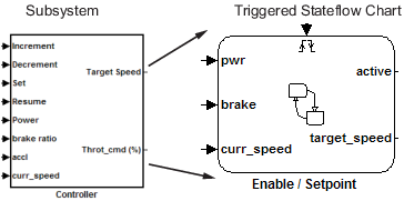
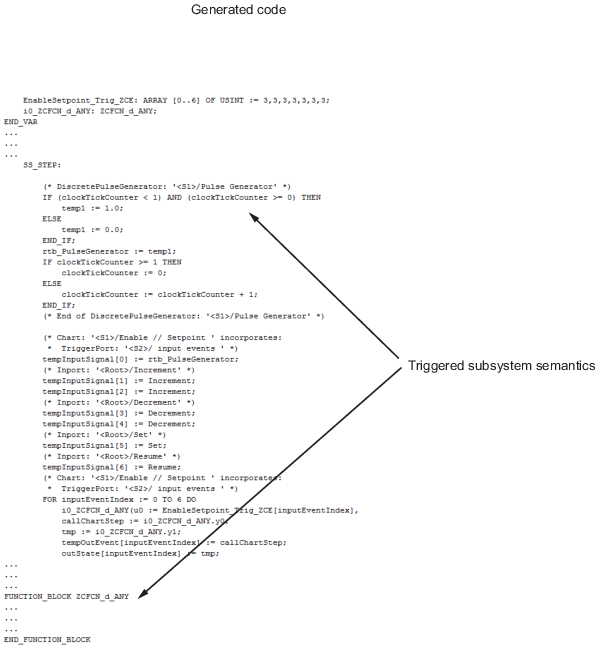
plcdemo_cruise_control.expfile open, open it in the MATLAB® editor.The following figure illustrates the mapping of the generated code to Structured Text components for a triggered Simulink subsystem. The first part of the figure shows the Controller subsystem and the triggered Stateflow® chart that it contains. The second part of the figure shows excerpts of the generated code. Notice the zero-crossing functions that implement the triggered subsystem semantics.