Simulate Passive Radar Sensors and Radar Interferences
This example shows how to model and simulate the output of active and passive radar sensors using radarDataGenerator. In this example, you observe how radio frequency (RF) interference impacts the detection performance of a radar. In addition, you use passive radar sensors to estimate the location and type of the RF interference.
Create Scenario
Assessing tracking performance for radars requires modeling a radio frequency (RF) scenario. The modeling workflow is as follows:
Generate RF emissions.
Propagate the emissions and reflect these emissions from platforms.
Receive the emissions, calculate interference losses, and generate detections.
In this example you perform each of these steps using a scenario consisting of three platforms:
Airborne platform flying north at 500 km/h from the bottom of the scenario
Airborne platform flying south at 600 km/h from the top of the scenario
Airborne platform flying east at 700 km/h in the middle of the scenario
First, create the scenario and set the scenario duration, then create the three airborne platforms.
scene = radarScenario;
scene.StopTime = 10; % s

% Platform 1: Airborne and northbound at 500 km/h
spd = 500*1e3/3600; % m/s
wp1 = [0 0 -6000];
wp2 = [spd*scene.StopTime 0 -6000];
toa = [0; scene.StopTime];
platform(scene,'Trajectory',waypointTrajectory('Waypoints',[wp1; wp2],'TimeOfArrival',toa));

% Platform 2: Airborne and southbound at 600 km/h
spd = 600*1e3/3600; % m/s
wp1 = [30e3+spd*scene.StopTime 0 -6000];
wp2 = [30e3 0 -6000];
toa = [0; scene.StopTime];
platform(scene,'Trajectory',waypointTrajectory('Waypoints',[wp1; wp2],'TimeOfArrival',toa));

% Platform 3: Airborne and eastbound at 700 km/h
spd = 700*1e3/3600; % m/s
wp1 = [10e3 1e3 -6000];
wp2 = [10e3 1e3+spd*scene.StopTime -6000];
toa = [0; scene.StopTime];
platform(scene,'Trajectory',waypointTrajectory('Waypoints',[wp1; wp2],'TimeOfArrival',toa));
Use theaterPlot to create a display showing the platforms in the scenario and their trajectories.
ax = axes;
theaterDisplay = theaterPlot('Parent',ax,'AxesUnit',["km" "km" "km"], 'XLim',[-10000 40000] , 'YLim', [-20000 20000], 'ZLim',[-1e7 1e7]);
view([90 -90]) % swap X and Y axis
patch('XData',[-10000 -10000 40000 40000],'YData',[-20000 20000 20000 -20000],'EdgeColor','none', 'FaceColor',[0.8 0.8 0.8],'DisplayName','Ground');

platPlotter = platformPlotter(theaterDisplay,'DisplayName','Platforms','MarkerFaceColor','k');
plotPlatform(platPlotter,vertcat(scene.platformPoses.Position));

trajPlotter = trajectoryPlotter(theaterDisplay,'DisplayName','Trajectories','LineStyle','-');
allTrajectories = cellfun(@(x) x.Trajectory.lookupPose(linspace(0,scene.StopTime,10)), scene.Platforms, 'UniformOutput', false);
plotTrajectory(trajPlotter,allTrajectories);
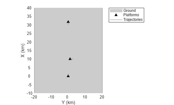
Radar Detection in the Presence of Interfering Emissions
Often, a radar operates in an environment where other undesirable RF emissions interfere with the waveforms emitted by the radar. When this occurs, the radar experiences a degradation in detection performance in the direction of the interfering signals. Attach an RF emitter to the platform at the bottom of the scenario (the first platform) and a radar to the platform at the top of the scenario (the second platform).
Create RF Emitter
Model an RF emission using a radarEmitter object. The emitter is in a forward-looking configuration with an azimuthal field of view of 20 degrees to include the two other platforms in the scenario. The effective isotropic radiated power (EIRP) sets the strength of the interfering signal. The waveform type is a user-defined value used to enumerate the various waveform types that are present in the scenario. For this scenario, use the value 0 to indicate a noise waveform type.
% Create the interference emitter.
rfEmitter = radarEmitter(1,'No scanning', ...
    'FieldOfView',[20 5], ...       % [az el] deg
    'EIRP',200, ...                 % dBi
    'CenterFrequency',300e6, ...    % Hz
    'Bandwidth',30e6, ...           % Hz
    'WaveformType',0)               % Use 0 for noise-like emissions
rfEmitter =
  radarEmitter with properties:

        EmitterIndex: 1
          UpdateRate: 1
            ScanMode: 'No scanning'

    MountingLocation: [0 0 0]
      MountingAngles: [0 0 0]

         FieldOfView: [2×1 double]
     MechanicalAngle: 0
           LookAngle: 0
        HasElevation: 0

                EIRP: 200
     CenterFrequency: 300000000
           Bandwidth: 30000000
        WaveformType: 0
      ProcessingGain: 0
Attach the emitter to the first platform.
platEmit = scene.Platforms{1};
platEmit.Emitters = rfEmitter
platEmit =
Platform with properties:
PlatformID: 1
ClassID: 0
Position: [0 0 -6000]
Orientation: [0 0 0]
Dimensions: [1×1 struct]
Trajectory: [1×1 waypointTrajectory]
PoseEstimator: [1×1 insSensor]
Emitters: {[1×1 radarEmitter]}
Sensors: {}
Signatures: {[1×1 rcsSignature]}
Create Monostatic Radar
Equip the second platform with a monostatic radar. Use radarDataGenerator to model this type of radar. First, create a monostatic radar using radarDataGenerator. Configure the radar's mounting orientation so that it scans the azimuth sector in front of its platform. Enable the INS input so that the radar can use the platform's pose estimator to output detections in scenario coordinates. Enable the interference input port so the interference signal created by the emitter above can be passed to the radar.
radar = radarDataGenerator(2, 'Sector', ...
    'DetectionMode', 'monostatic', ...
    'UpdateRate', 12.5, ...          % Hz
    'FieldOfView', [2 10]);          % [az el] deg

radar.MountingAngles = [0 0 0];      % [Z Y X] deg
radar.HasINS = true;
radar.InterferenceInputPort = true;
radar.DetectionCoordinates = 'scenario'
radar =
  radarDataGenerator with properties:

              SensorIndex: 2
               UpdateRate: 12.5000
            DetectionMode: 'Monostatic'
                 ScanMode: 'Mechanical'
    InterferenceInputPort: 1
       EmissionsInputPort: 0

         MountingLocation: [0 0 0]
           MountingAngles: [0 0 0]

              FieldOfView: [2 10]
                LookAngle: [0 0]
              RangeLimits: [0 100000]

     DetectionProbability: 0.9000
           FalseAlarmRate: 1.0000e-06
           ReferenceRange: 100000

       TargetReportFormat: 'Clustered detections'

  Show all properties
Attach the radar to the second platform.
platRadar = scene.Platforms{2};
platRadar.Sensors = radar;
Update the display to show the platforms, the radar, and the emitter in the scenario.
emitterColor =  [0.9290 0.6940 0.1250];
radarColor = [0 0.4470 0.7410];
platEmitPlotter = platformPlotter(theaterDisplay,'DisplayName', 'RF emitter','Marker','d','MarkerFaceColor',emitterColor);
platRadarPlotter = platformPlotter(theaterDisplay,'DisplayName','Monostatic radar','Marker','d','MarkerFaceColor',radarColor);
platPlotter.DisplayName = 'Targets';
clearData(platPlotter);
covPlotter = coveragePlotter(theaterDisplay,'Alpha',[0.2 0]);
detPlotter = detectionPlotter(theaterDisplay,'DisplayName','Radar detections','MarkerFaceColor',radarColor);
title('Radar Detection With an Interfering Emitter');

plotPlatform(platRadarPlotter, platRadar.pose.Position);
plotPlatform(platEmitPlotter, platEmit.pose.Position);
plotPlatform(platPlotter, scene.Platforms{3}.pose.Position);
plotCoverage(covPlotter, coverageConfig(scene), [-1 2], {emitterColor, radarColor});
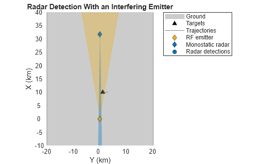
In the preceding figure, the platform carrying the forward-looking radar is shown as a blue diamond, and the radar's current field of view is a blue region originating from the platform. At the bottom of the figure, the platform carrying the interfering RF emission is shown as a yellow diamond, and the emitter's current field of view is a corresponding yellow region. Platforms without any emitters or sensors attached to them are referred to as targets and are displayed as black triangles.
Simulate Monostatic Detections
In multirate scenarios, you can either find an update rate that is a common divider of all the sensors and emitter rates defined in the scenario or you can use the continuous update, which automatically advances the scenario to the next valid update time when you call advance.
scene.UpdateRate = 0
scene =
  radarScenario with properties:

      IsEarthCentered: 0
           UpdateRate: 0
       SimulationTime: 0
             StopTime: 10
     SimulationStatus: NotStarted
            Platforms: {[1×1 radar.scenario.Platform]  [1×1 radar.scenario.Platform]  [1×1 radar.scenario.Platform]}
       SurfaceManager: [1×1 radar.scenario.SurfaceManager]
    AtmosphereManager: [1×1 radar.scenario.AtmosphereManager]
For each step in the following loop, use:
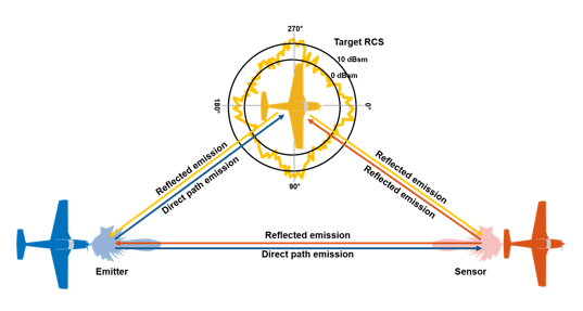
advanceto move all of the platforms according to their trajectories.emitto update the transmit direction of emissions fromplatEmit.propagateto propagate the emissions directly to each platform in the scenario that lies within the emitter's field of view. Each platform that receives a direct path emission generates a single-bounce reflection that is also propagated to every other platform as a reflected emission.detectto generate detections from the emissions received atplatRadar.
The following figure shows the propagation of emissions from the emitter to the radar sensor.
% Set the random seed for repeatable results.
rng(2018);

plotDets = {};
while advance(scene)

    % Emit the RF signal.
    txEmiss = emit(scene);

    % Reflect the emitted signal off the platforms in the scenario.
    reflEmiss = propagate(scene, txEmiss);

    % Generate detections from the monostatic radar sensor.
    [dets, config] = detect(scene, reflEmiss);

    % Reset detections every time the radar completes a sector scan.
    if config.IsScanDone
        % Reset
        plotDets = dets;
    else
        % Buffer
        plotDets = [plotDets;dets]; %#ok<AGROW>
    end

    % Update display with current platform positions, beam positions and detections.
    plotPlatform(platRadarPlotter, platRadar.pose.Position);
    plotPlatform(platEmitPlotter, platEmit.pose.Position);
    plotPlatform(platPlotter, scene.Platforms{3}.pose.Position);
    plotCoverage(covPlotter, coverageConfig(scene), [-1 2], {emitterColor, radarColor});
    if ~isempty(plotDets)
        allDets = [plotDets{:}];
        % Extract column vector of measurement positions
        meas = [allDets.Measurement]';
        plotDetection(detPlotter,meas);
    end
end
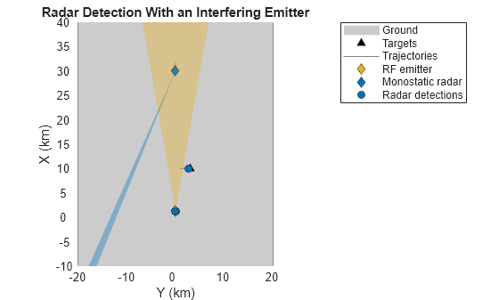
The preceding figure shows that the radar (shown in blue) is only able to detect the target in the middle of the scenario. The detections are shown as blue, filled circles, and are made whenever the radar's field of view (that is, the beamwidth) sweeps across the target. However, when the radar's beam sweeps across the emitting platform (shown in yellow), no detections are generated, since the interference generated by this platform prevents detection by the radar.
Passive Detection of RF Emissions
In the preceding section, the radar is unable to detect the location of the emitting platform because the emissions from that platform mask the radar's own emissions. However, such strong emissions can be detected and identified by passive sensors that listen for RF emissions. These sensors are often referred to as electronic support measures (ESM). These sensors typically listen across a broad range of frequencies and attempt to identify unique emitters, the direction of arrival of the emissions from those emitters, and whenever possible, the type of waveform used by the emitter.
Create an ESM Sensor
Reuse the scenario from the previous section, but replace the monostatic radar on the first platform with an ESM sensor. Use radarDataGenerator to model the ESM sensor and ensure that the sensor is configured so that its center frequency and bandwidth includes the RF spectrum of the emitter. Otherwise, it will be unable to detect the emitter.
restart(scene);
esm = radarDataGenerator(1,'No scanning', ...
    'DetectionMode','ESM', ...
    'UpdateRate',12.5, ...          % Hz
    'MountingAngles',[0 0 0], ...   % [Z Y X] deg
    'FieldOfView',[30 10], ...      % [az el] deg
    'CenterFrequency',300e6, ...    % Hz
    'Bandwidth',30e6, ...           % Hz
    'WaveformTypes',0, ...          % Detect the interference waveform type
    'HasINS',true)
esm =
  radarDataGenerator with properties:

         SensorIndex: 1
        EmitterIndex: 1
          UpdateRate: 12.5000
       DetectionMode: 'ESM'
            ScanMode: 'No scanning'

    MountingLocation: [0 0 0]
      MountingAngles: [0 0 0]

         FieldOfView: [30 10]

      FalseAlarmRate: 1.0000e-06

  Show all properties
Replace the radar on the second platform with the ESM sensor.
platESM = scene.Platforms{2};
platESM.Sensors = esm;
Update the visualization accordingly.
platRadarPlotter.DisplayName = "ESM sensor";
esmColor = [0.4940 0.1840 0.5560];
platRadarPlotter.MarkerFaceColor = esmColor;
% use a helper to add an angle-only detection plotter
delete(detPlotter);
esmDetPlotter = helperAngleOnlyDetectionPlotter(theaterDisplay,'DisplayName','ESM detections','Color',esmColor,'LineStyle','-');
clearData(covPlotter);

plotCoverage(covPlotter, coverageConfig(scene), [-1 1], {emitterColor, esmColor});
title('Passive detection of RF emissions');
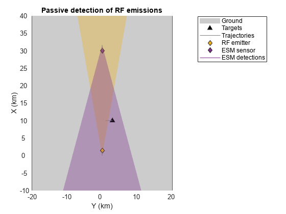
In the preceding figure, the radar is replaced by an ESM sensor mounted on the second platform. The ESM sensor's field of view is shown in magenta and includes both the emitting and target platforms.
Simulate ESM Detections
Now simulate detections using the ESM sensor instead of the radar. Notice that because the ESM sensor is a passive sensor, it is unable to localize the emitting platform, but indicates the direction of arrival of the platform's emissions. These angle-only detections are shown as rays originating from the ESM sensor toward the emitting platform.
% Set the random seed for repeatable results.
rng(2018);

plotDets = {};
snap = [];
while advance(scene)

    % Emit the RF signal.
    txEmiss = emit(scene);

    % Reflect the emitted signal off the platforms in the scenario.
    reflEmiss = propagate(scene, txEmiss);

    % Generate detections from the ESM sensor.
    [dets, config] = detect(scene, reflEmiss);

    % Reset detections every time the radar completes a sector scan.
    if config.IsScanDone
        % Reset
        plotDets = dets;
    else
        % Buffer
        plotDets = [plotDets;dets]; %#ok<AGROW>
    end

    % Update display with current platform positions, beam positions, and detections.
    plotPlatform(platRadarPlotter, platRadar.pose.Position);
    plotPlatform(platEmitPlotter, platEmit.pose.Position);
    plotPlatform(platPlotter, scene.Platforms{3}.pose.Position);
    plotCoverage(covPlotter, coverageConfig(scene), [-1 1], {emitterColor, esmColor});
    plotDetection(esmDetPlotter,plotDets);

    % Record the reflected detection at t = 2 seconds.
    snap = getSnap(ax, scene.SimulationTime, 2, snap);
    drawnow
end
title('RF emitter detected by an ESM sensor');
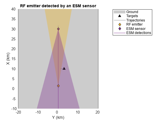
The ESM sensor detects the RF emissions and estimates their direction of arrival. This estimate is shown by the magenta line originating from the sensor and closely passing by the emitter. The angle estimate is noisy, which is why the line does not pass directly through the location of the emitter.
The ESM sensor classifies the waveform types in its reported detections. For this emitter, it reports the noise waveform type used by the emitter: 0.
dets{1}.ObjectAttributes{1}ans = struct with fields:
TargetIndex: 1
EmitterIndex: 1
WaveformType: 0
SNR: 173.8303
Notice that the signal-to-noise ratio (SNR) of the emitted signal detected by the sensor is very large, 185 dB. Because the RF emitter has high power, reflections of the emitted waveform off the target are also detected by the ESM sensor. This is seen at 2 seconds into the simulation, when the target lies within the field of view of the emitter.
figure; imshow(snap.cdata);
title('Emitter and Target Detected by an ESM Sensor');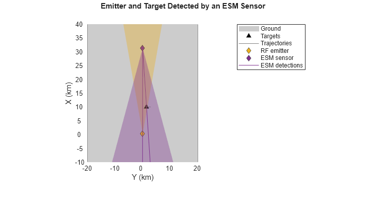
The preceding figure shows emissions that are detected from both the emitter and the target, as the target receives energy from the emitter and re-emits that waveform back into the scenario, causing it to be detected by the ESM sensor as well.
Passive Detection of Monostatic Radars
Monostatic radars also emit waveforms into the scenario. Passive detection of these emissions is sometimes desirable. To do so, you must model both the emitting and sensing portions of the radar separately. The emitter generates the waveforms that become part of the scenario's RF emissions. These waveforms can then be detected by other sensors, such as an ESM sensor.
Reuse the same scenario from before. For this scenario, attach a monostatic radar to the platform at the top of the scenario (the second platform), and attach an ESM sensor to the platform at the bottom of the scenario (the first platform). The middle platform remains a target with no emitters or sensors attached to it.
restart(scene);
Create a monostatic radar by modeling both the emitting and sensing portions of the sensor. Use radarEmitter to model the monostatic radar emitter. For this scenario, use 1 to indicate the waveform type used by this radar. The waveform type is an enumeration defined by the user to represent the different kinds of waveforms simulated in the scenario. The waveform enumeration enables emitters and sensors to know how to process these waveforms to generate detections. For example, if an emitter has a waveform type of 1 and a sensor includes this in its waveform list, then the sensor knows how to process the emitter's emissions (for example, using a matched filter) and realizes the processing gain associated with that waveform.
% Create the emitter for the monostatic radar.
radarTx = radarEmitter(2,'Sector', ...
    'UpdateRate',12.5, ...          % Hz
    'MountingAngles',[0 0 0], ...   % [Z Y X] deg
    'FieldOfView',[2 10], ...       % [az el] deg
    'CenterFrequency',300e6, ...    % Hz
    'Bandwidth',3e6, ...            % Hz
    'ProcessingGain',50, ...        % dB
    'WaveformType',1)               % Use 1 to indicate this radar's waveform.
radarTx =
  radarEmitter with properties:

             EmitterIndex: 2
               UpdateRate: 12.5000
                 ScanMode: 'Mechanical'

         MountingLocation: [0 0 0]
           MountingAngles: [0 0 0]

              FieldOfView: [2×1 double]
    MaxMechanicalScanRate: 75
     MechanicalScanLimits: [-45 45]
          MechanicalAngle: 0
                LookAngle: 0
             HasElevation: 0

                     EIRP: 100
          CenterFrequency: 300000000
                Bandwidth: 3000000
             WaveformType: 1
           ProcessingGain: 50
Use radarDataGenerator to model the sensing portion of the radar that receives the RF emissions in the scenario, identifies the emissions that correspond to the monostatic emitter's waveform type, and generates detections from these received emissions. Emissions that do not match the emitter's waveform type are treated as interference.
When using radarDataGenerator to model the sensing portion of a monostatic radar, set the DetectionMode property of the sensor to Monostatic. This tells the sensor to use the emitter's configuration when processing the received RF emissions. The EmissionsInputPort property must also be set true to enable detections on radarEmission objects.
radarRx = radarDataGenerator(2, ...
    'DetectionMode','Monostatic', ...
    'EmissionsInputPort',true, ...
    'EmitterIndex',radarTx.EmitterIndex, ...
    'HasINS',true, ...
    'DetectionCoordinates','Scenario')
radarRx =
  radarDataGenerator with properties:

              SensorIndex: 2
             EmitterIndex: 2
            DetectionMode: 'Monostatic'
    InterferenceInputPort: 0
       EmissionsInputPort: 1

              RangeLimits: [0 100000]

           FalseAlarmRate: 1.0000e-06

  Show all properties
Attach the radar emitter and sensor to the second platform.
platRadar = scene.Platforms{2};
platRadar.Emitters = radarTx;
platRadar.Sensors = radarRx;
Reuse the ESM sensor from before, but set the list of known waveform types for the ESM sensor to include the waveform emitted by the radar. If the radar's waveform type is not known to the ESM sensor, it will not be detected.
% Add the radar's waveform to the list of known waveform types for the ESM sensor.
esm.WaveformTypes = [0 1];

% Attach the ESM sensor to the first platform.
platESM = scene.Platforms{1};
platESM.Emitters = {}; % Remove the emitter.
platESM.Sensors = esm;
Update the display to show both monostatic detections and ESM detections.
detPlotter = detectionPlotter(theaterDisplay,'DisplayName','Radar detections','MarkerFaceColor',radarColor);
platRadarPlotter.DisplayName = 'Monostatic radar';
platRadarPlotter.MarkerFaceColor = radarColor;
platEmitPlotter.DisplayName = 'ESM sensor';
platEmitPlotter.MarkerFaceColor = esmColor;
clearData(esmDetPlotter);
clearData(covPlotter);
covcon = coverageConfig(scene);
plotCoverage(covPlotter, covcon([1 3]) , [1 -2], {esmColor, radarColor});
title(ax,'Passive detection of a monostatic radar');
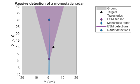
The preceding figure shows the radar scanning an azimuth sector in front of its platform, which includes both the target platform as well as the platform carrying the ESM sensor. The radar generates detections for both of these platforms when its field of view (shown in blue) sweeps over their location. However, when the radar's beam passes over the location of the ESM sensor, the ESM sensor detects the radar and indicates the estimated position by drawing a line originating from the sensor.
% Set the random seed for repeatable results.
rng(2018);

platforms = scene.Platforms;
numPlat = numel(platforms);


plotDets = {};
snap = [];
while advance(scene)

    % Emit the RF signal.
    [txEmiss, txConfigs] = emit(scene);

    % Reflect the emitted signal off the platforms in the scenario.
    reflEmiss = propagate(scene, txEmiss);

    % Generate detections from the sensors.
    [dets, config] = detect(scene, reflEmiss, txConfigs);

    % Reset detections every time the radar completes a sector scan.
    if txConfigs(end).IsScanDone
        % Reset
        plotDets = dets;
    else
        % Buffer
        plotDets = [plotDets;dets];%#ok<AGROW>
    end

    % Update display with current platform positions, beam positions, and detections.
    plotPlatform(platRadarPlotter, platRadar.pose.Position);
    plotPlatform(platEmitPlotter, platEmit.pose.Position);
    plotPlatform(platPlotter, scene.Platforms{3}.pose.Position);
    covcon = coverageConfig(scene);
    plotCoverage(covPlotter, covcon([1 3]) , [1 -2], {esmColor, radarColor});
    plotDetection(esmDetPlotter,plotDets);
    plotMonostaticDetection(detPlotter,plotDets);

    % Record the reflected detection at t = 5.6 seconds.
    snap = getSnap(ax, scene.SimulationTime, 5.6, snap);
    drawnow
end
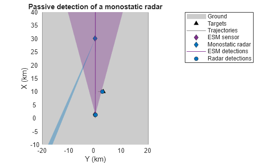
Detections from the monostatic radar modeled using radarEmitter and radarDataGenerator are shown as filled, blue circles near the target and the platform equipped with the ESM sensor. The ESM sensor is also able to detect the radar, as is indicated by the angle-only detection shown as a line originating from the ESM sensor and passing near the radar platform.
figure; imshow(snap.cdata);
title('Radar and Target Detected by an ESM Sensor');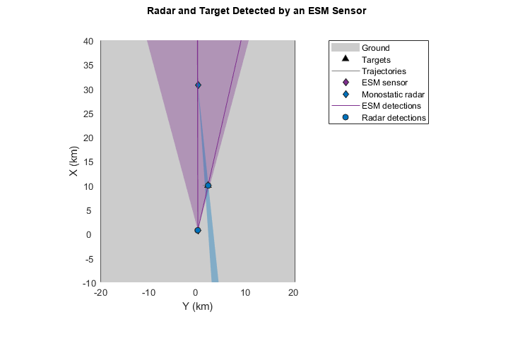
Because of the high power (EIRP) of the radar's emissions, the emitted energy is reflected off the target toward the ESM platform. Consequently, the ESM sensor detects the target platform when the radar emitter's field of view sweeps past the target platform while the target is still inside of the ESM sensor's field of view.
Supporting Functions
getSnap records a snapshot of an axis at a given snap time.
function snap = getSnap(hAx, curTime, snapTime, prevSnap)
if ~isempty(prevSnap)
    snap = prevSnap;
elseif curTime >= snapTime && curTime < snapTime + 0.05
    hAx.Title.Visible = 'off';
    snap = getframe(hAx.Parent);
    hAx.Title.Visible = 'on';
else
    snap = [];
end
end
plotMonostaticDetection parses detections to plot only monostatic detections with a detectionPlotter.
function plotMonostaticDetection(plotter, dets)
if ~isempty(dets)
    % Pass only monostatic detections to the detectionPlotter
    radarDetId = cellfun(@(x) x.SensorIndex == 2, dets);
    if any(radarDetId)
        % Extract measurement positions for the monostatic radar
        radarDets = [dets{radarDetId}];
        meas = [radarDets.Measurement]';
        plotDetection(plotter,meas);
    end
end
end