Simulate Construction Vehicles in Unreal Engine for Material Handling
This example shows how to quickly prototype a Construction Site Scene with standard construction vehicles using ready-made assets. In this example, a backhoe loads bricks into a dump truck. This example uses these toolboxes:
Robotics System Toolbox™— Control the backhoe in Simulink® with
rigidBodyTreeobject andinverseKinematics(IK) System object™.Simulink 3D Animation™— Provide Unreal Engine® simulation environment.
Robotics System Toolbox Offroad Autonomy Library™— Add the backhoe and dump truck blocks from this support package in the Simulink and simulate in the Unreal Engine.
To use Simulation 3D Physics Dump Truck and Simulation 3D Physics Backhoe blocks, you must download and install the Robotics System Toolbox Offroad Autonomy Library support package from Add-On Explorer. For more information about installing add-ons, see Get and Manage Add-Ons.
This example shows the basic construction scene assembly and simulation. To implement a more advance workflow, see:
Simulate and Control Vehicles in Unreal Engine
This example uses Simulink blocks from the Robotics System Toolbox Offroad Autonomy Library to simulate vehicles in a construction scene. The construction site scene consists of an offroad terrain and contains Unreal assets such as bricks, walls, buildings, and so on. Further, the dump truck and backhoe vehicles are placed side-by-side in the Unreal scene.
Simulation Flow
In this model, you use a scheduler to move the backhoe through four distinct stages:
At the start, the backhoe is in a initial joint positions, which means that the links, such as the front and rear buckets, are in their default pose.
Once you initiate the trajectory, the rear bucket moves to an open position in front of the bricks.
Next, the bucket moves to a close position, where it scoops the bricks.
Once the bucket picks up the bricks, it moves over the truck bed and deposits the bricks there.
Set Up Simulink Model
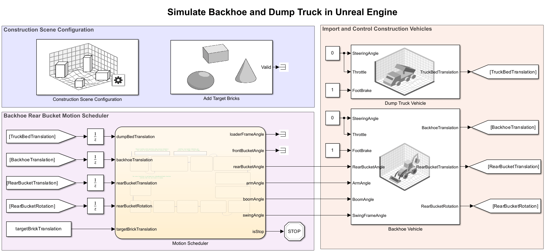
The Simulink model consists of these subsystems:
Construction Scene ConfigurationImport and Control Construction VehiclesBackhoe Rear Bucket Motion Scheduler
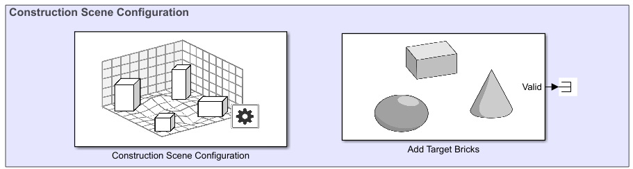
Construction Scene Configuration
Download Construction Site Scene
To begin, check the maps available in the server.
sim3d.maps.Map.server
             MapName                                        Description                              Version
    __________________________    _______________________________________________________________    _______

    "Suburban scene"              "a suburban area beyond the city's border"                           "1"
    "Offroad pit mining scene"    "An open pit mine with haul roads and terraced levels"               "1"
    "Construction site scene"     "A construction site scene with walls, buildings and materials"      "1"
Download the Construction site scene from the server.
sim3d.maps.Map.download("Construction site scene")Map is successfully downloaded and is up-to-date
Check if the downloaded map is available in your local machine.
sim3d.maps.Map.local
             MapName                                        Description                              Version
    __________________________    _______________________________________________________________    _______

    "Offroad pit mining scene"    "An open pit mine with haul roads and terraced levels"               "1"
    "Construction site scene"     "A construction site scene with walls, buildings and materials"      "1"
Configure Construction Scene in Unreal Engine
Open the Simulink model.
open_system("ConstructionVehicleUnreal.slx");Select the Unreal Construction Site Scene using Simulation 3D Scene Configuration block. Next, configure and position the bricks using the Simulation 3D Actor (Simulink 3D Animation) block. The setupworld.m script is called within the Simulation 3D Actor block, which simplifies the process of placing multiple bricks in various locations.
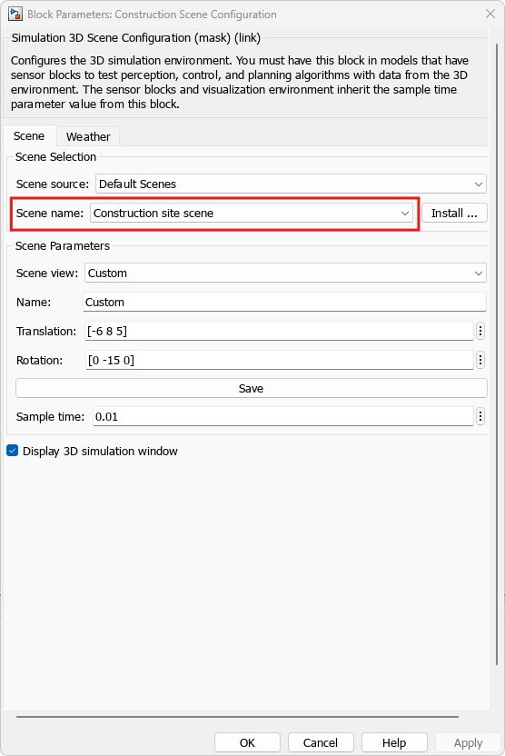
To use downloaded construction scene, the Scene source parameter is set to Default Scenes and Construction site scene is selected in the Scene name field.
Generate the brick locations and use to add target bricks in the scene and target intermediate, pick-up joint position calculation.
targetBrickTranslation = helperGenerateTargetLocation();
Import and Control Construction Vehicles
The Simulation 3D Physics Dump Truck and Simulation 3D Physics Backhoe blocks import the dump truck and backhoe Unreal assets into the construction scene. The SteeringAngle and Throttle inputs are zero as both vehicles remain stationary during simulation and the Simulink model only simulates the motion of the rear bucket of the backhoe. Further, control the backhoe's rear bucket by adjusting the RearBucketAngle, ArmAngle, BoomAngle, and SwingFrameAngle. The backhoe rigidBodyTree object under the backhoe task scheduler computes these parameter values.

Backhoe Rear Bucket Motion Scheduler
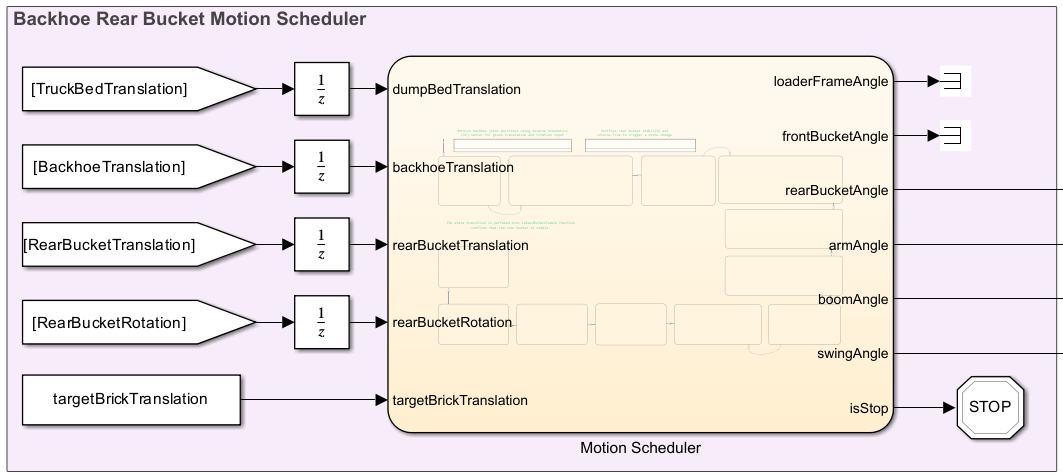
The backhoe asset rigidBodyTree controls the rear bucket joints of the backhoe.
RigidBodyTree for Backhoe asset
This model uses robotics tools to determine poses for the rear bucket of the backhoe. To do that, you need a kinematic model of the backhoe. A rigidBodyTree object relates the joint angles to the poses of the backhoe's components, such as the front bucket, loader frame, swing frame, arm, boom, and rear bucket.
In this example, you import a rigidBodyTree object from a URDF using importrobot. The URDF model was created by exporting backhoe asset from an FBX file using Phobos, a third-party Blender plug-in.
In a rigidBodyTree object, the joint configuration defines joint angles, which specifies the positions of the different bodies in the robot model. In this example, you specify a rigidBodyTree object as an input to an inverse kinematics (IK) solver, which is a tool that accepts a target bucket pose and returns a joint configuration.
Load a precomputed rigid body tree representation of a backhoe.
load("backhoeRigidBodyTree.mat");Visualize rigid body tree representation of a backhoe.
backhoeRBT.show();
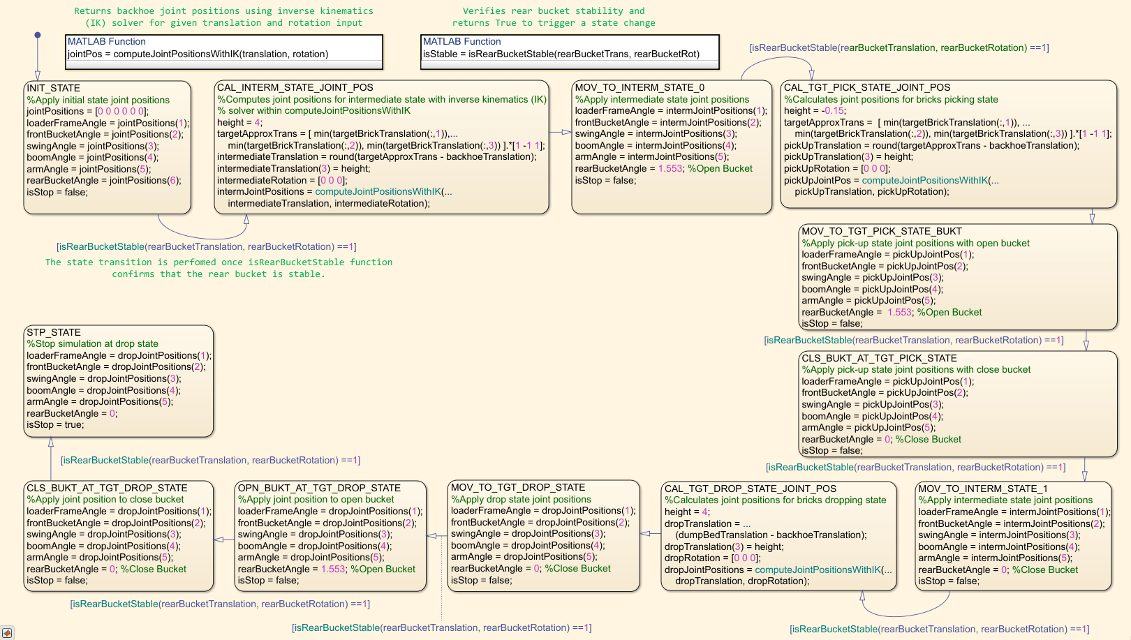
Motion Scheduler
The rear bucket motion consists of following major states, which are decided based on ground truth target brick location, backhoe location, and truck bed location.
INIT_STATE : The backhoe remains in its initial joint position until the
isRearBucketStablefunction confirms the rear bucket is stable.CAL_INTERM_STATE_JOINT_POS : Computes the intermediate joint positions for a backhoe using a
rigidBodyTreemodel and an inverse kinematics (IK) solver within thecomputeJointPositionsWithIKfunction, based on the target location and current backhoe position.MOV_TO_INTERM_STATE_0 : The rear bucket transitions from the home joint position to the calculated intermediate joint position, and then its stability is checked using the
isRearBucketStablefunction before proceeding to the next stateCAL_TGT_PICK_STATE_JOINT_POS : Calculates the pick-up joint position for the rear bucket to reach a low ground position suitable for picking up bricks
.MOV_TO_TGT_PICK_STATE_BUKT : The rear bucket, kept open, and moves to the brick location for easy collection.
CLS_BUKT_AT_TGT_PICK_STATE : The rear bucket closes to collect bricks.
MOV_TO_INTERM_STATE_1 : The rear bucket returns to the intermediate joint position to avoid truck bed collision.
CAL_TGT_DROP_STATE_JOINT_POS : Determines the target drop joint position using the current truck bed location and the current backhoe position.
MOV_TO_TGT_DROP_STATE : The rear bucket moves to the target drop location.
OPN_BUKT_AT_TGT_DROP_STATE : The rear bucket opens upon reaching the drop location to release bricks into the truck bed.
CLS_BUKT_AT_TGT_DROP_STATE : The rear bucket closes during after releasing the bricks into the truck bed.
STP_STATE : Ends the simulation.
This model uses a simple approach where the system passes a few known ground-truth poses directly to a controller. A more advanced approach requires modeling the simulation world and using a planner to guarantee a collision-free and time-optimal trajectory. For more information on that approach, see the Plan Collision-Free Path for Excavator Arm in MATLAB With Lidar Data example.
Perform Simulation
Run simulation and visualize the simulation.
sim("ConstructionVehicleUnreal");
Visualize rigidBodyTree Collision Geometry in Unreal
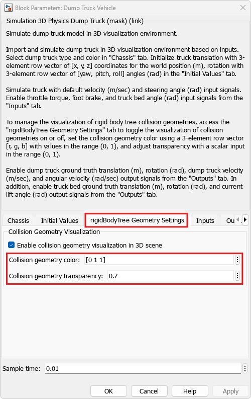
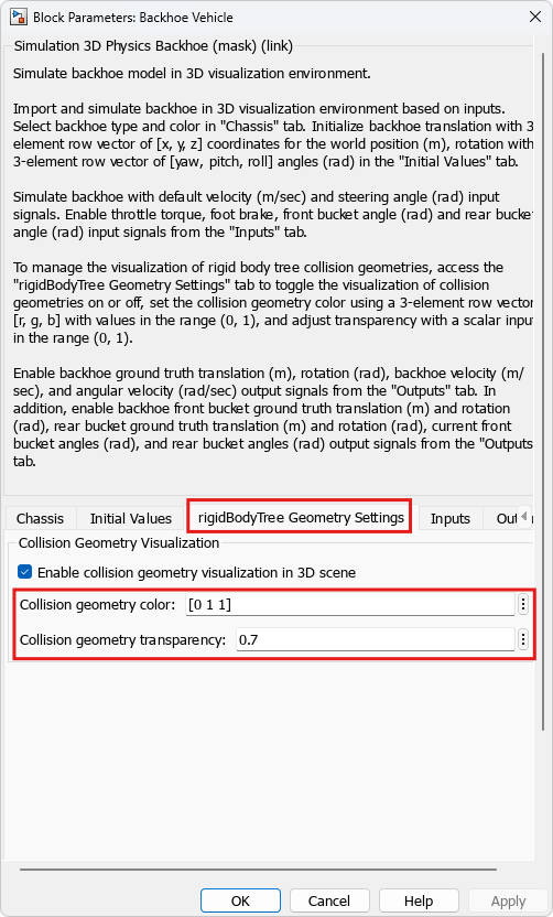
To enable rigidBodyTree collision geometry visualization in Unreal, perform following setting in the rigidBodyTree Collision Settings tab from the Simulation 3D Physics Dump Truck and Simulation 3D Physics Backhoe blocks. Further, modify rigidBodyTree collision geometry color and transparency by specifying values in the Collision geometry color and Collision geometry transparency field.
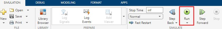
Re-run the simulation by clicking Run button.
Visualize rigidBodyTree collision geometry in Unreal.
This simulation example demonstrates the power of Unreal Engine combined with Simulink for creating realistic and efficient construction vehicle operations. By following the steps outlined here, you can simulate complex vehicle dynamics and operations, leading to improved design and planning in construction projects.
See Also
Simulation 3D Physics Dump Truck | Simulation 3D Physics Backhoe