Plan Excavator Trajectory in ROS 2 Using Asynchronous Service Server
This example demonstrates how to use an asynchronous ROS 2 service server in Simulink® to plan and execute collision-free trajectories for a simulated autonomous excavator. It builds on the Simulate Earth Moving with Autonomous Excavator in Construction Site (Robotics System Toolbox) example by modifying the trajectory planning section to use a ROS 2 service client that sends trajectory requests and receives obstacle-free paths from a service server. The asynchronous service server responds immediately to incoming requests, containing the excavator’s current and goal joint configurations, selected object, and a lidar point cloud and returns a planned path that the trajectory generator converts into executable motion.
In this variation, the Plan Trajectory for Excavator module, highlighted in red, uses ROS 2 services to request and receive collision-free paths from the asynchronous service server, while the other modules remain the same as in the base example.
Prerequisites
ROS Toolbox™ — Establish ROS 2 service communication between service-server and service-client.
Refer to the base example Simulate Earth Moving with Autonomous Excavator in Construction Site (Robotics System Toolbox) for a detailed overview of how the required products are used in the application.
Download dependencies
To run the example, download the construction site scene for Unreal Engine and an excavator model for Simscape. You can download these dependencies using helper files provided with this example. The helpers check if these files are available locally, otherwise they download them.
helperDownloadConstructionScene
helperDownloadExcavatorDesign
Generate and Deploy Custom Messages
This example uses a custom message package planner_msgs which contains a service file PathPlanner.srv. The service planner_msgs/PathPlanner is used in this example to find the path for the excavator. In this example the message package is available in the custommsgs folder. Generate the custom messages in MATLAB using ros2genmsg to use the custom message package.
ros2genmsg('custommsgs')Excavator Model Overview
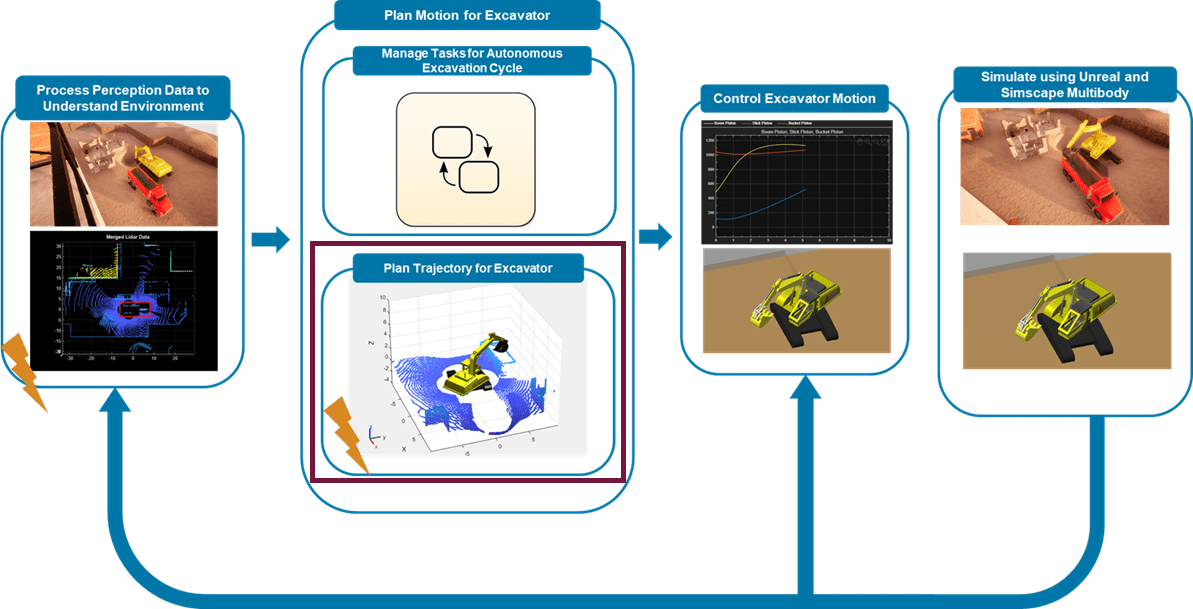
The top-level Simulink model is organized into four high-level modules, each responsible for a part of the autonomous excavator workflow:
Process Perception Data: Convert lidar point clouds and ground-truth data from Unreal into a 3-D occupancy map for collision checking.
Plan Motion for Excavator: Use Stateflow® to manage excavation stages and trigger trajectory planning at each stage.
Control Excavator Motion: Apply PID controllers to actuate Simscape™ Multibody™ pistons and track desired joint angles.
Simulate Excavator and Construction Site: Simulate the excavator in Simscape Multibody and the environment in Unreal Engine®, including objects such as dump trucks.
open_system("followPlannedTrajectorySimscapeUnreal.slx");Plan Motion for Excavator
In the model, the Plan Motion for Excavator module includes two main parts, as shown in the diagram below.
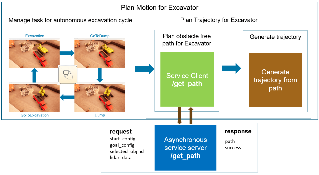
Manage Tasks for Autonomous Excavation Cycle: Uses Stateflow to manage the stages (Excavation, GoToDump, Dump, GoToExcavation). For each stage, it triggers the Trajectory Planner function-call subsystem in the Plan Trajectory for Excavator module. This part is unchanged from the base example.
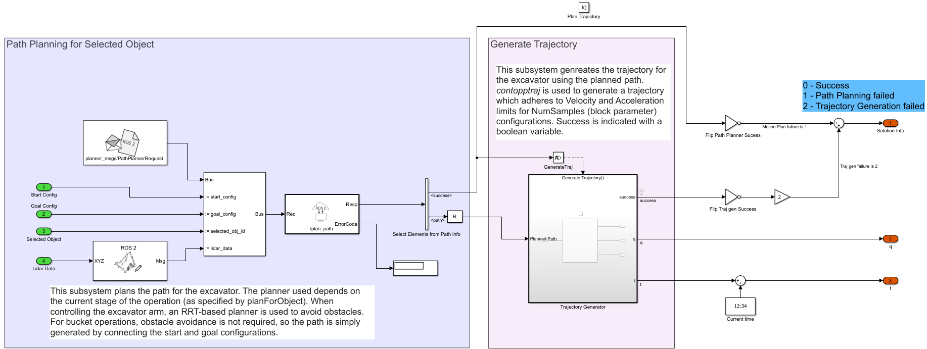
Plan Trajectory for Excavator: Includes the Trajectory Planner function-call subsystem, which this example modifies to act as a ROS 2 service client. The subsystem sends the current joint angles, goal configuration, selected object, and merged lidar point cloud to an asynchronous ROS 2 service server. The server immediately returns an obstacle-free path, which the Generate Trajectory block converts into a collision-free trajectory that respects velocity and acceleration constraints.
Implement Asynchronous Service Server
Open the Simulink model that implements the asynchronous ROS 2 service server to plan the excavator trajectory.
open_system("PathPlanningServer.slx");
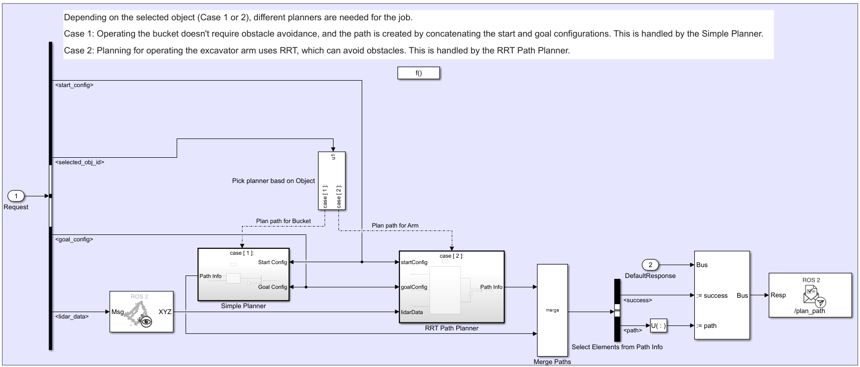
This model contains the Asynchronous Service Server which plans the path for the excavator. As mentioned in the previous section, the service server receives current configuration, goal configuration and the selected object along with the merged lidar point cloud as request and returns the planned-path as response. The 'Receive Service Request' callback subsystem is a function call subsystem which is triggered immediately when the Service Server receives a service request. This subsystem contains the algorithm to generate the obstacle free path for the excavator as mentioned in below picture.
The service server executes one of two path planners, depending on the excavation task:
RRT-based planner: Uses a manipulatorRRT object with a rigidBodyTree to plan arm motions. The planner avoids obstacles represented by an occupancyMap3D and restricts certain joint angles to prevent spoil from spilling.
Simple planner: Connects start and goal configurations directly for bucket operations where collision checking is unnecessary.
The Selected Object signal specifies which planner runs at runtime. For example, the task manager selects the RRT planner when the excavator arm must move to the dump site and selects the simple planner when the bucket scoops soil. For a complete description of the excavation cycle and task transitions, see the base example.
You can then build and load the model to generate and deploy the ROS 2 node on the local host.
Build and Deploy the Asynchronous Service Server as ROS 2 node
Deploy the service server model (PathPlanningServer.slx) in local host.
% Generate and deploy standalone application for the model
slbuild("PathPlanningServer");

Simulate Excavator model
When the server is up, simulate the excavator model that contains the service client, and validate the planned trajectories. To simulate and visualize the scene in Unreal Engine and Simscape Multibody Mechanics Explorer, click Run on the Simulation tab of the Simulink toolstrip. During simulation, at the start of each excavation stage, the service client sends an asynchronous request to the service server and receives an immediate response. Because the server is configured for asynchronous execution, it processes requests as soon as they arrive rather than using sample-time-based polling and it can return the planned path without delay.
sim("followPlannedTrajectorySimscapeUnreal.slx");
Conclusion
This example demonstrates how to model an asynchronous ROS 2 service server in Simulink for real-time, asynchronous trajectory planning of a simulated autonomous excavator. By configuring the service server to respond immediately to incoming requests, you reduce communication latency and avoid unnecessary CPU usage associated with periodic polling.