Code Verification and Validation with External Mode
This example shows you how to use Simulink® Coder™ Support Package for NXP™ FRDM-KL25Z for code verification and validation using external mode.
Introduction
In this example you how to configure a Simulink model to run a simulation in external mode.
The Simulink external mode feature enables you to accelerate the process of parameter tuning by letting you change certain parameter values while the model is running on target hardware, without stopping the model. When you change parameter values from within Simulink, the modified parameter values are communicated to the target hardware immediately. You can monitor the effect of the parameter tuning activity by viewing algorithm signals on scopes or displays in Simulink.
Prerequisites
We recommend completing Getting Started with Simulink Coder Support Package for NXP FRDM-KL25Z Board.
Required Hardware
To run this example you need this hardware:
On Mac:
NXP FRDM-KL25Z board
USB type A to Mini-B cable
USB TTL-232 cable - TTL-232R 3.3V
On Windows®:
NXP FRDM-KL25Z board
USB type A to Mini-B cable
USB TTL-232 cable - TTL-232R 3.3V (This is required only when you use UART1 or UART2 serial communication interface)
This example is tested with the FTDI Friend USB TTL-232R 3.3V adapter.
OS Specific Limitations
On Mac:
External mode simulation is supported only through UART1 or UART2.
On Windows:
External mode simulation is supported through available UART communication interfaces.

Task - External Mode
In this task, you run a model in external mode. When you are prototyping and developing an algorithm, it is useful to monitor and tune the algorithm while it runs on hardware. The external mode feature in Simulink enables this capability.
The Simulink Coder Support Package for NXP FRDM-KL25Z Board supports three different serial communication interfaces for External mode: UART0, UART1, and UART2. On Mac platforms, external mode over UART0 is supported only on Mac version 'El Capitan'.
The UART0 serial communication interface is accessible through the mini USB port labeled with openSDA on the NXP FRDM-KL25Z board or the onboard GPIO Pins for UART0. Using UART0 through the mini USB port does not require additional cables or hardware, besides a USB type A to Mini-B cable that is used to connect the NXP FRDM-KL25Z board to the development computer. To use the UART0 through the GPIO pins on NXP FRDM-KL25Z board, additional hardware is required, as mentioned below for the UART1 and UART2 serial communication interfaces.
The UART1 and UART2 serial communication interfaces are accessible only through pins on the NXP FRDM-KL25Z board. Using these interfaces requires additional hardware, for example, a USB TTL-232R adapter, to perform external mode simulations.
1. Open model freedomboard_external_mode.
This model is preconfigured for the NXP FRDM-KL25Z target. To learn how to set up a model for this target, see Getting Started with Simulink Coder Support Package for NXP FRDM-KL25Z Board.
2. Choose a serial communication interface. In Configuration Parameters > Hardware Implementation > Target Hardware Resources > External mode > Select hardware UART, select UART0, UART1, or UART2.
As an example, see the settings for model freedomboard_external_mode in this figure.

3. Choose the Tx and Rx GPIO pins for the selected serial communication interface:
After you select the serial communication interface, in *Configuration Parameters > Hardware Implementation > Target Hardware Resources > Selected Target, choose the pins for the UART selected in step 2.
As an example, for UART1, see the settings for model freedomboard_external_mode in this figure.

4. Connect to the hardware. Based on the serial interface you selected, follow these steps:
For UART0:
Connect a USB cable from your development computer to the OpenSDA mini-B USB connector of the NXP FRDM-KL25Z board.
If the TX Pin selected for UART0 is
PTE20orPTD7, connect the RX pin of the USB TTL-232R adapter to the selected TX pin on the NXP FRDM-KL25Z board. If the TX pin selected for UART0 isPTA2 (USBTX), the USB cable from your development computer for the OpenSDA mini-B USB connector of the NXP FRDM-KL25Z Board is sufficient.If the RX Pin selected for UART0 is
PTE21or PTD6, connect the TX pin of the USB TTL-232R adapter to the selected RX pin on the NXP FRDM-KL25Z board. If the RX pin selected for UART0 isPTA1 (USBRX), the USB cable from your development computer for the OpenSDA mini-B USB connector of the NXP FRDM-KL25Z Board is sufficient.
For UART1:
Connect a USB cable from your development computer to the OpenSDA mini-B USB connector of the NXP FRDM-KL25Z Board.
Connect ground pin of the USB TTL-232R adapter to one of the GND pins on the NXP FRDM-KL25Z board.
Connect the RX pin of the USB TTL-232R adapter to the TX pin, selected in Configuration Parameters for UART1, on the NXP FRDM-KL25Z board
Connect the TX pin of the USB TTL-232R adapter to the RX pin, selected in Configuration Parameters for UART1, on the NXP FRDM-KL25Z board.
Connect the USB side of the USB TTL-232R adapter to your development computer.
For UART2:
Connect a USB cable from your development computer to the OpenSDA mini-B USB connector of the NXP FRDM-KL25Z board.
Connect the ground pin of the USB TTL-232R adapter to one of the GND pins on the NXP FRDM-KL25Z board.
Connect the RX pin of the USB TTL-232R adapter to the TX pin, selected in Configuration Parameters for UART2, on the NXP FRDM-KL25Z board.
Connect the TX pin of the USB TTL-232R adapter to the RX pin, selected in Configuration Parameters for UART2, on the NXP FRDM-KL25Z board.
Connect the USB side of the USB TTL-232R adapter to your development computer.
After you complete the preceding steps, a new serial COM port should be available for use on your development computer.
5. Find the COM port associated with your adapter cable.
On Windows:
Open Device Manager.
Expand the Ports tab.
If you selected
UART1orUART2for serial external mode communication interface, note the COM port associated with the USB TTL-232R adapter.If you selected
UART0for the serial external mode communication interface, and selectedPTA2(USBTX)andPTA1(USBRX)for the TX and RX pins, respectively, note the OpenSDA COM port associated with NXP FRDM-KL25Z board by following steps described in Install Drivers for NXP FRDM-KL25Z Board.If you selected
UART0for the serial external mode communication interface, and the TX and RX pins selected for the same are other thanPTA2(USBTX)andPTA1(USBRX)respectively, note the COM port associated with the USB TTL-232R adapter.
On Mac:
In a terminal window, enter the command
ls /dev/cu.*.Note the serial port name associated with the USB TTL-232R adapter.
6. Open your model configured for code generation on an NXP FRDM-KL25Z board. In Configuration Parameters > Hardware Implementation > Target Hardware Resources > External mode > Serial port, set the Serial port parameter to the COM port number noted in the previous step.
For example, on Windows, set Serial port to COM27. On Mac enter /dev/cu.usbmodem1442.

7. Set the baud rate. Click the selected UART group and enter the baud rate as this figure shows:

8. Click Apply and close the Configuration Parameters dialog box.
9. In the model window toolstrip, from the Simulinkk Mode menu, select External.
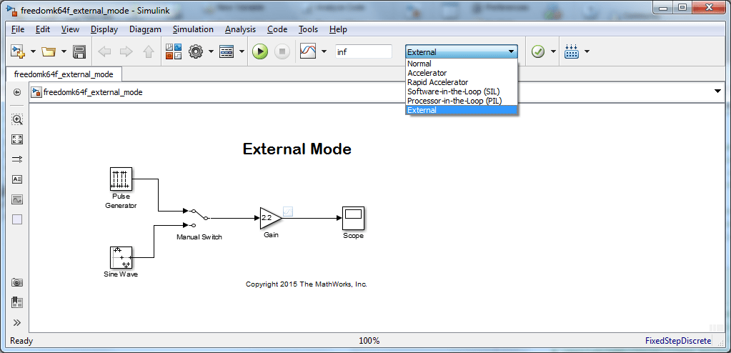
10. Start the external mode by clicking Run.

When the model is built and downloaded onto the target, the external mode simulation starts. The entire model runs on the target.
To change the input source while simulation is running, double-click the Manual Switch block.
To change the signal
gain, double-click the Gain block.To view the external mode simulation results, double-click the Scope block.
11. Stop external mode simulation.
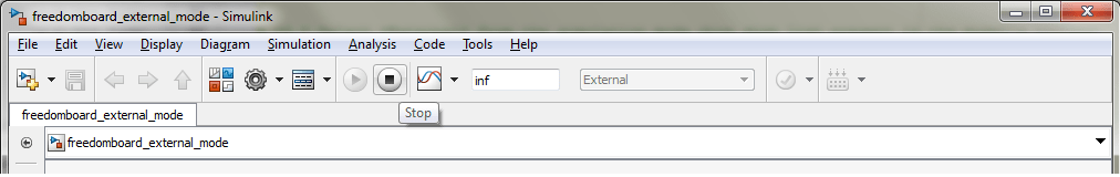
Stopping external mode simulation terminates code running on the NXP FRDM-KL25Z. Before you can start another external mode simulation, run the generated code again. To rerun the generated code, on the NXP FRDM-KL25Z board, press Reset.
Things to Remember While Setting Up the Model to Run in External Mode
Make sure that the COM port number that you enter in the External mode pane is correct.
In the Model explorer, navigate to the Code -> External Mode Control pane and click Signal and Triggering. The default value of the Duration parameter under the Trigger Options Section is
1000. Change this value to 5 as the memory on the target is not enough to store 1000 data values. For more information on the Duration parameter, see External Mode Simulation with TCP/IP or Serial Communication.For UART0, recommended baud rates for external mode communication are 9600, 19200, and 57600.