Hardware Implementation Pane
Hardware Implementation Pane Overview
Specify the options for creating and running applications on target hardware.
Configuration
Configure hardware board to run Simulink® model.
In the Simulink Editor, select Simulation > Model Configuration Parameters.
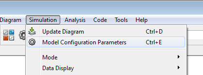
In the Configuration Parameter dialog box, click Hardware Implementation.

Set the Hardware board parameter to match your target hardware board.
Apply the changes.
Hardware board
Select the type of hardware upon which to run your model.
Changing this parameter updates the Configuration Parameters dialog box so it only displays parameters that are relevant to your target hardware.
After installing support for your target hardware, reopen the Configuration Parameters dialog box and select your target hardware.
To run the model on your NXP™ board, select NXP FRDM-KL25Z.
Settings
Default:
None
NoneThis setting means your model has not been configured to run on target hardware. Choose your target hardware from the list of options.
Get more...Select this option to start Support Package Installer and install support for additional hardware.
Build Options
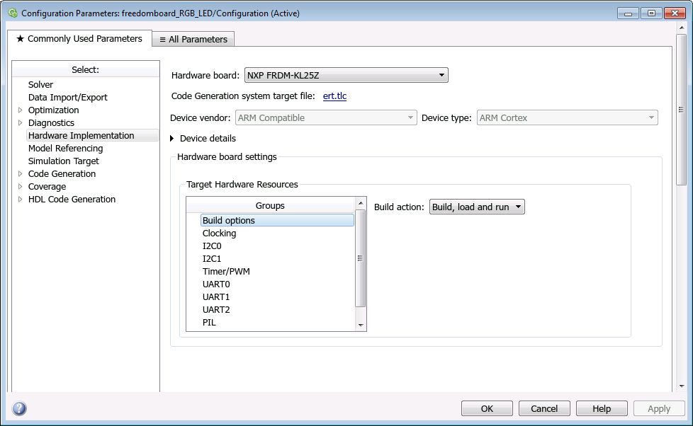
To specify how the build process takes place during code generation, select build options.
- Build action
Specify whether you want only a build action or build, load, and run actions during code generation.
Default:
Build, load and runBuild— Select this option if you want to build the code during the build process.Build, load and run— Select this option to build, load, and run the generated code during the build process.
Clocking
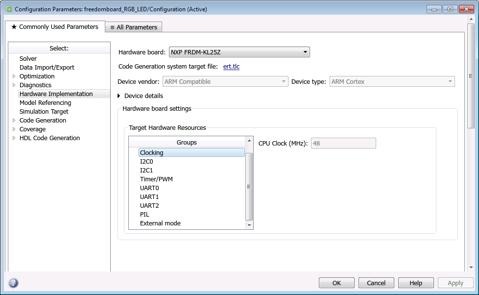
- CPU Clock (MHz)
This option is for the CPU clock frequency of the FRDM-KL25Z processor on the target hardware.
Note
This parameter appears dimmed. The value of this parameter is set to
48MHz.
I2C0 and I2C1
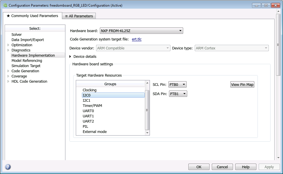
- SCL Pin
Select an SCL pin for I2C communication.
I2C0
Default:
PTB0PTB0, PTB2, PTC8, PTE24I2C1
Default:
PTE1PTE1, PTC1, PTC10- SDA Pin
Select an SDA pin for I2C communication.
I2C0
Default:
PTB1PTB1, PTB3, PTC9, PTE25I2C1
Default:
PTE0PTE0, PTC2, PTC11, PTA4
Timer/PWM
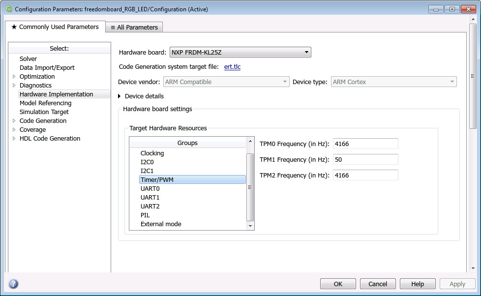
- TPM0 Frequency (in Hz)
Specify the frequency for the TPM0 timer.
Default:
4166Hz- TPM1 Frequency (in Hz)
Specify the frequency for the TPM1 timer.
Default:
50Hz- TPM2 Frequency (in Hz)
Specify the frequency for the TPM2 timer.
Default:
4166Hz
UART0, UART1, and UART2
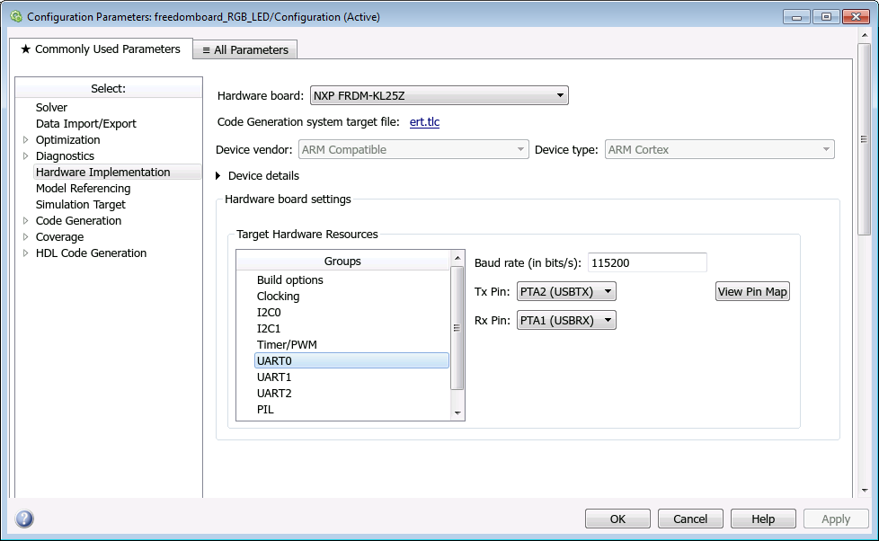
- Baud rate (in bits/s)
Specify the baud for UARTx serial interfaces.
Default:
115200- Tx Pin
Select a Tx pin for serial communication.
UART0
Default:
PTA2 (USBTX)PTA2 (USBTX), PTE20, PTD7, No connectionUART1
Default:
PTC4PTC4, PTE0, No connectionUART2
Default:
PTD5PTD5, PTE22, PTD3, No connection- Rx Pin
Select an Rx pin for serial communication.
UART0
Default:
PTA1 (USBRX)PTA1 (USBRX), PTE21, PTD6, No connectionUART1
Default:
PTC3PTC3, PTE1, No connectionUART2
Default:
PTD4PTD4, PTE23, PTD2, No connection
PIL

- Select hardware UART
Select the target UART port for PIL communication. After selecting an UART port, go to the selected UART in Configuration Parameters > Hardware Implementation pane > UARTx and select the Tx and the Rx pins.
Default:
UART0- Serial port
Enter the serial port for PIL communication.
Default:
COM1
External mode
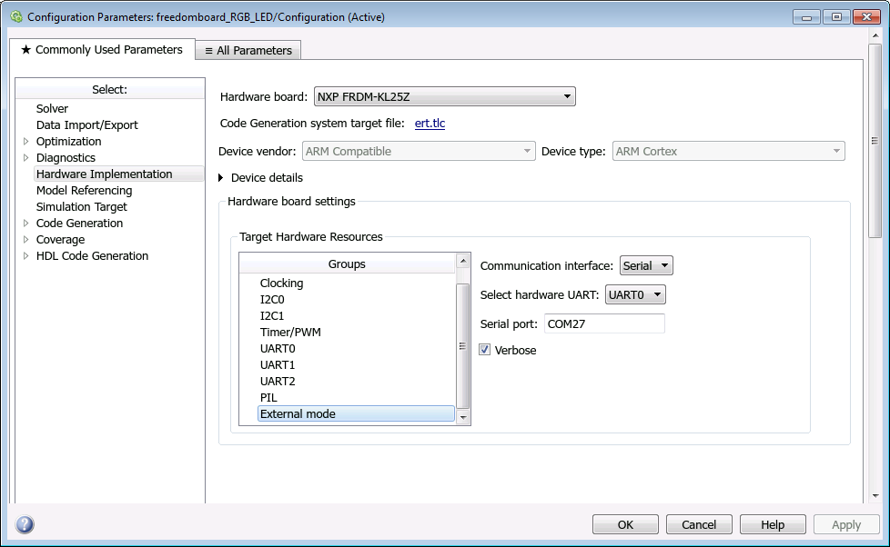
- Communication interface
Use the serial option to run your model in the external mode with serial communication.
Default:
serial- Select hardware UART
Select the target UART port for external mode communication. After selecting an UART port, go to the selected UART in Configuration Parameters > Hardware Implementation pane > UARTx and select the Tx and the Rx pins.
Default:
UART0Note
The target UART0 port for external mode communication works only in Windows® and Mac OS X El Capitan operating systems.
- Serial port
Enter the serial port for external mode communication.
Default:
COM27- Verbose
Select this check box to view the external mode execution progress and updates in the Diagnostic Viewer or in the MATLAB® Command Window.