Link-Level CCSDS SCPPM Simulation Using Deep Space Poisson Channel
This example shows how to perform bit error rate (BER) analysis for the Consultative Committee for Space Data Systems (CCSDS) serially concatenated pulse position modulation (SCPPM) chain using a deep space Poisson channel. The example also describes the information processing in the SCPPM encoder, passing the encoded data through the Poisson optical channel, and then decoding the received soft bits using the SCPPM decoder. This example uses the SCPPM encoder defined in CCSDS 142.0-B-1 section 3.8 [1] and the SCPPM decoder defined in Coded Modulation for the Deep-Space Optical Channel section III.A [2]. The optical channel used is a binary-input, soft-output, deep space pulse position modulation (PPM) Poisson channel, as defined in Coded Modulation for the Deep-Space Optical Channel section IV [2].
Processing Chain
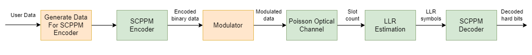
To analyze the BER performance for a CCSDS SCPPM chain, follow these steps.
Generate SCPPM encoder input from the user data. Add the cyclic redundancy check (CRC) and termination bits to this user data.
Encode the generated data using the SCPPM encoder. The output is a sequence of SCPPM codewords where each codeword consists of 15120/
mPPM symbols.mis the modulation order, specified as an integer in the range [2, 8]. A PPM symbol is an integer value corresponding to each grouping ofmbinary code symbols.Modulate the SCPPM codewords using the M-ary PPM. Each code symbol is mapped to a binary vector of length
M(whereM=2^m) by placingM—10s and a single1into one of the possible positions, based on the code symbol value.Transmit the modulated binary data over a deep space optical channel that is modeled as a Poisson point process. This channel adds Poisson-distributed noise to the signal, and calculates the estimated photon count in each slot.
Calculate the bit-wise log-likelihood ratios (LLRs) of the input signal using the estimated photon count obtained from the channel.
Simultaneously demodulate and decode the signal at the receiver, using the SCPPM decoder, to recover the user data.
This block diagram illustrates the optical communications channel.
SCPPM Encoder
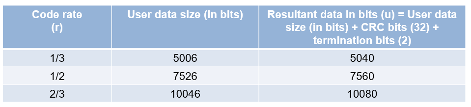
To generate data for the SCPPM encoder, first generate random frames of input data. The table shows the supported information block sizes corresponding to the code rate, as described in CCSDS 142.0-B-1 section 3.4.1 [1]. Append 32 CRC binary digits to the end of each information block, as described in CCSDS 142.0-B-1 section 3.6 [1]. These CRC bits help in block error detection and SCPPM decoder termination. Append two 0s to the CRC-attached information block to terminate the outer convolutional encoder of the SCPPM encoder. The resultant encoder input data, u, has 34 additional bits (32 CRC bits + 2 termination bits) as compared to the user data.
As specified in CCSDS 142.0-B-1 section 3.6 [1]:
The generator polynomial for the CRC algorithm is fixed to
The initial states of the internal shift register are fixed to 1.
crc32Cfg = crcConfig(... Polynomial="x^32+x^29+x^18+x^14+x^3+1", ... InitialConditions=1,DirectMethod=true); infoSize =7526; % Information block size without CRC
This figure shows the individual components of the SCPPM encoder.
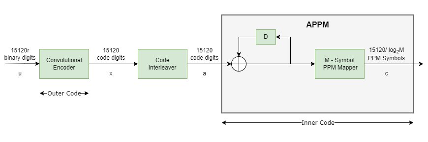
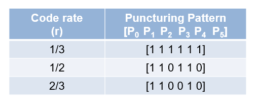
The SCPPM encoder consists of two constituent codes, referred to as the outer and inner codes, connected by a bit interleaver. The outer code is a short-constraint-three-length convolutional code defined by [5, 7, 7] in octal notation. This table shows the outer convolutional encoder puncturing patterns for the supported code rates, as described in CCSDS 142.0-B-1 section 3.8.2.3.1 [1].
The inner code consists of an accumulator ( filter) and a memoryless PPM modulator, together referred to as an accumulator pulse position modulation (APPM) code. Each SCPPM encoder input block (u) is of length 15120r, encoded by the outer convolutional encoder, and yields a code sequence (x) of length 15120. Interleave this code, bit wise, to produce a sequence (a) that the accumulator encodes. Map the output sequence from the accumulator to M-ary PPM symbols (c), an M-length vector, where M is a managed parameter with values from the set {4, 8, 16, 32, 64, 128, 256}, where every m = log2(M) binary digits are grouped to form one PPM symbol. Each PPM symbol is an integer in the range [0, M—1].
m =6; M = 2^m; % M-ary PPM
Deep Space Poisson Channel
For this example, consider an optical communications system that uses direct photon detection with a high-order PPM. An M-order PPM uses a time interval that is divided into M possible pulse locations, but places only a single pulse into one of the possible positions. The information to be transmitted determines the position of the pulse. After modulation, the overall length in bits is . Pass this modulated data through the channel.
The receiver, focuses light on the detector. The detector responds to individual photons. Consider these parameters at the detector.
k — Estimated photon count within each slot
— Average number of signal photon incident on the detector per second (including both pulsed and non-pulsed periods)
— Average number of noise photon incident per second
— Quantum efficiency of the detector
— Slot time
1/
M— Duty cycle (denotes the average number of pulses transmitted per )
For a PPM channel, the output of a photon-counting detector is modeled as a Poisson process, where the average number of signal photons per pulse is = , and the average number of noise photons per slot is = . Assuming the pulse energy is captured in a slot, also denotes the mean number of signal photons per pulsed slot. For a deep space optical Poisson channel, calculate the LLR of each slot by using these formulas:
The probability of receiving k, given the pulse is not sent in that slot : .
The probability of receiving k, given the pulse is sent in that slot : .
LLR of each slot :.
Ts = 32;                                    % PPM slot width in nanoseconds
pps = linspace(-30.25,-29.88,7)';           % Average number of signal photons per nano second (ns/(M*Ts))
ns = power(10,pps/10)*M*Ts;                 % Average number of signal photons per pulsed slot
nb = 0.2;                                   % Average number of noise photons per slot

% Initialize Poisson channel System object
chanObj = dsocPoissonChannel(NumNoisePhotons=nb);
SCPPM Decoder
This figure shows the SCPPM decoder, as described in Coded Modulation for the Deep-Space Optical Channel section III.A [2]. Each encoder maps an input sequence, either u or a, into an output sequence, either x or c. In an iterative decoding process, each encoder has a corresponding decoder. Conventionally, the modulation and error control coding (ECC) are decoded sequentially, with the demodulator sending its results to the ECC decoder. In SCPPM decoding, consider the modulation and ECC as a single large code, which maps user information bits directly to the symbols transmitted on the channel, and uses an iterative demodulator-decoder to decode this large code. Once the underlying Trellis descriptions of the outer convolutional code, inner accumulator, and modulation are formulated, standard forward-backward algorithms can be used. Numerical results show that this is a powerful technique to obtain near-capacity performance.
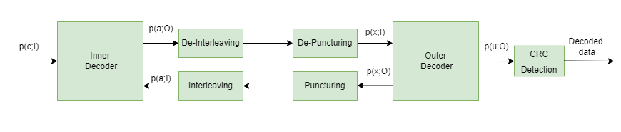
The inner decoder takes the input a priori likelihoods of input of the inner encoder, a, and output of the inner encoder, c, and produces an updated likelihood of a. Similarly, the outer decoder takes the input a priori likelihoods of output of outer encoder, x, and produces updated likelihoods of u and x. Iterations between the inner and outer code terminate based on a stopping rule. The SCPPM decoder terminates the iterations if CRC passes, or if it reaches the maximum number of decoding iterations. If CRC passes, the decoder considers it as a valid frame. Otherwise, the decoder considers it as an invalid frame.
numFrames = 20;
maxIter = 12;
numErrFrames = zeros(length(ns),1);
berEst = zeros(length(ns),1);
errorRate = comm.ErrorRate;

for itr = 1:length(ns)
    rng("default")
    chanObj.NumSignalPhotons=ns(itr);
    for frmIdx=1:numFrames
        % Generate input data
        data = randi([0 1],infoSize,1);
        crcData = crcGenerate(data,crc32Cfg); % Generate CRC
        msgIn = [crcData; 0; 0];              % Add termination bits

        % Perform SCPPM encoding
        [encSym,info] = ccsdsSCPPMEncode(msgIn,m);
        r = info.OuterEncoderCodeRate;

        % M-ary PPM Modulation
        modOut = zeros(length(encSym)*M,1);
        mapIndex = (0:length(encSym)-1)'*M + encSym + 1;
        modOut(mapIndex) = 1;

        % Pass through Poisson channel
        slotCount = chanObj(modOut);
        receivedCode = log(1+(ns(itr)/nb))*slotCount - ns(itr);

        % SCPPM decoding
        [decData,errFrames] = ccsdsSCPPMDecode(...
            receivedCode,r,m,maxIter);
        errorStats = errorRate(int8(msgIn),decData);
        numErrFrames(itr) = numErrFrames(itr)+errFrames;
    end
    berEst(itr) = errorStats(1);
    release(errorRate)
    release(chanObj)
end
Plot BER
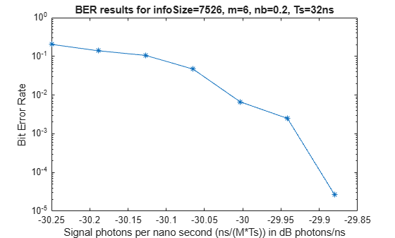
Visualize the BER results. Plot the average number of signal photons per nano second on the x-axis and bit error rate on the y-axis.
semilogy(pps,berEst,'-*')
xlabel("Signal photons per nano second (ns/(M*Ts)) in dB photons/ns")
ylabel("Bit Error Rate")
title("BER results for infoSize="+num2str(infoSize)+", m="+num2str(m)+", nb="+num2str(nb)+", Ts="+num2str(Ts)+"ns")
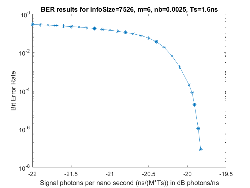
This figure shows the BER analysis for an SCPPM decoder over a Poisson channel, for 1500 frames with information size = 7526, code rate (r) = 1/2, average number of noise photons per slot (nb) = 0.0025, slot time (Ts) = 1.6, and modulation order (m) = 6.
References
[1] The Consultative Committee for Space Data Systems. Optical Communications Coding and Synchronization, Recommended Standard, Issue 1. CCSDS 142.0-B-1. Washington, D.C.: CCSDS, August 2019. https://ccsds.org/index.php?gf-download=2025%2F01%2F%2F142x0b1.pdf.
[2] Moision, B., and J. Hamkins. “Coded Modulation for the Deep-Space Optical Channel: Serially Concatenated Pulse-Position Modulation.” Interplanetary Network Progress Report 42–161 (May 1, 2005): 1–25. https://ui.adsabs.harvard.edu/abs/2005IPNPR.161T...1M.
[3] Moision, B., and J. Hamkins. “Deep-Space Optical Communications Downlink Budget: Modulation and Coding.” Interplanetary Network Progress Report 42–154 (August 1, 2003): 1–28. https://ui.adsabs.harvard.edu/abs/2003IPNPR.154K...1M.
[4] Cheng, M. K., M. A. Nakashima, B. E. Moision, and J. Hamkins. “Optimizations of a Turbo-Like Decoder for Deep-Space Optical Communications.” Interplanetary Network Progress Report 42–168 (February 1, 2007): 1–31. https://ui.adsabs.harvard.edu/abs/2007IPNPR.168G...1C.