NavIC Waveform Generation
This example shows how to generate the Standard Positioning Service (SPS) data and complex baseband waveform for the Navigation with Indian Constellation (NavIC) satellite navigation system. Data is spread using coarse acquisition codes (C/A-codes) or interleaved Z4 (IZ4) linear codes. This example generates a NavIC waveform as specified in the ISRO-IRNSS-ICD-SPS-1.1 [1] and ISRO-IRNSS-SPS-ICD-L1-v1.0 [2] standards. To design a navigation receiver for NavIC signals, you must test the receiver with a received signal. Because you cannot control transmitter and channel parameters, a signal received from a satellite is not useful for initial testing of the receiver. This example generates the NavIC waveform in MATLAB® so that you can configure the waveform as required, and supports these waveforms.
You can also add impairments, by enabling the EnableImpairments option, to generate a realistic waveform. For more details, refer the Further Exploration section.
NavIC Waveform Generation Workflow
Generate a NavIC signal using these steps.
Generate NavIC data bits by using the configuration parameters described in the
HelperNavICConfigobject. The configuration generates data bits at rates of 50 bits per second (bps) and 100 bps for L5/S and L1, respectively.Spread these low-rate data bits by using high-rate spreading codes. The NavIC standards [1] and [2] use C/A-codes and IZ4 codes, respectively, as the spreading codes.
NavIC L5/S uses C/A-codes at a chip rate of 1.023 mega chips per second (Mcps). The user data bits modulate these codes to form the SPS data signal. NavIC L1 uses IZ4 codes at a chip rate of 1.023 Mcps, and the overlay codes component is at a chip rate of 100 chips per second.
Modulate the spread data bits of NavIC L5/S by using the binary offset carrier (BOC) and binary phase shift keying (BPSK) modulation schemes. Modulate NavIC L1 by using the BOC and synthesized BOC (SBOC) modulation schemes.
Interplex the navigation signals to generate a NavIC waveform.
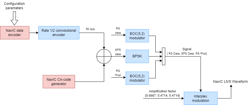
This figure shows the block diagram of the NavIC L5/S waveform generator. Here, RS stands for restricted service, an authorized encryption service offered by NavIC. The example uses random signals for RS data and RS pilot, as information about these signal is not available in the public domain.
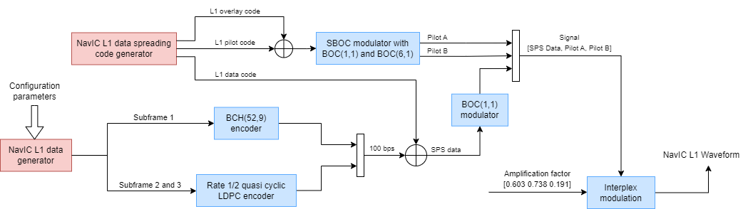
This diagram shows the NavIC L1 waveform generator.
NavIC Signal Structure
The standards [1] and [2] describe the transmission of NavIC signals on three frequencies: L1(1575.42 MHz), L5 (1176.45 MHz), and S (2492.028 MHz). The code-division-multiple-access (CDMA) technique enables the user to differentiate between the satellites even though all NavIC satellites transmit on the same frequency. As of R2024a, NavIC is an evolving navigation system, and its signal structure is being expanded to improve the navigation system performance in the future. NavIC has also recently started supporting operation on the L1 band. This section provides information about the NavIC signal structures.
L5/S Signal Structure
NavIC transmits navigation data as SPS in both L5 and S bands. A frame is 2400 symbols long and consists of four subframes. Each subframe carries a 16-bit sync code and 292 bits of data. These 292 bits of data result in 584 bits of encoded data after forward error correction (FEC) using a convolutional encoder. The data transmission rate is 50 bps, and thus takes 12 seconds to transmit a subframe and 48 seconds to transmit the entire frame. This figure shows the frame structure of the NavIC L5/S data.

L1 Signal Structure
NavIC L1 transmits two pilot signals and one data signal as the SPS. A frame is 1800 symbols long and consists of three subframes. NavIC L1 has a non-uniform number of symbols in each of the subframes.
The first subframe is 52 symbols, obtained by encoding 9 bits of time of interval (TOI) information using a Bose Choudhari Hocquenghem (BCH) encoder.
Subframe 2 and subframe 3 are 600 bits and 274 bits in length, respectively. These result in 1200 and 548 symbols, respectively, of encoded data after FEC coding using a rate LDPC encoder.
The data transmission rate for NavIC L1 is 100 bps, and thus takes 18 seconds to transmit the entire frame. This figure shows the frame structure of the NavIC L1 data.

Modulation Scheme
The NavIC carrier modulation scheme is comprised of BOC and BPSK. This section provides detailed information about the usage of these modulation schemes in NavIC L5/S and L1.
L5/S Signals
NavIC supports two services: SPS (open service) and RS (authorized access service). The SPS signal is BPSK-modulated in both the L5 and S bands. The RS signals consist of BOC-modulated data and pilot signals. The data channel and pilot channel in RS are BOC(5,2) modulated. These three signals (SPS, RS data, and RS pilot) modulate each NavIC L5/S signal transmission.
L1 Signals
Unlike NavIC L5/S, which transmits one SPS signal, NavIC L1 transmits three SPS signals. In L1, NavIC modulates these three signals, consisting of two pilot signals and one data signal, using SBOC.
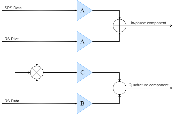
When you pass any of L1 or L5/S signals through a power amplifier operated in the saturation region the output produces a non-constant envelope signal. To mitigate this, NavIC uses interplex modulation that adds a fourth signal to produce a constant envelope signal at the output of the amplifier. This diagram shows the interplex modulation technique for NavIC L5/S. Here, A, B, and C are the amplification factor values for the corresponding signals.
Enable the ShowVisualizations option to visualize the waveform spectra. Enable the WriteWaveformToFile option to write the complex baseband waveform to a file, if required. Enable the EnableImpairments option to generate an impaired waveform. Set the WaveformType option to the specific band required to generate the desired waveform. In this example, the default waveform type is NavIC L5-SPS, with visualizations enabled. This example also does not include impairments or write the waveform to a file, by default.
ShowVisualizations =true; WriteWaveformToFile =
false; EnableImpairments =
false; WaveformType =
"NavIC L5-SPS";
Specify the satellite PRN indices as a vector of integers in the range [1, 7].
PRNID = [3 4 5];
Simulation Configuration
Generating a NavIC waveform for all of the navigation data can take a lot of time and memory. To generate quick results and a visualization, this example generates the waveform for only one bit of the navigation data. You can also generate the waveform for a set number of data bits by specifying the value of numNavDataBits. Use navDataBitStartIndex to specify a part of the navigation data from which to generate the waveform.
% Set this value to control the number of navigation data bits in the
% generated waveform.
numNavDataBits = 1;
% Set this value to 1 to generate the waveform from the first bit of the
% navigation data.
navDataBitStartIndex = 1321;
% Set this value to define the sample rate of generated waveform. To
% retrieve all of the information of the generated waveform, set this value
% as equal to or greater than 24.5520 MHz for NavIC L1-SPS waveform. For
% NavIC L5/S-SPS waveforms, set this value equal to or greater than 10.023
% MHz.
fs = 10*1.023e6;

% Set signal to noise ratio as a scalar or vector corresponding to each
% satellite signal.
SNRdB = 1;     % In dB
% Set signal delay as a scalar or vector corresponding to each satellite
% signal.
sigDelay = 0;  % In seconds
% Set frequency offset as a scalar or vector corresponding to each
% satellite signal.
freqOffset = 0;% In Hz
Download NavIC L1 Initial Conditions Data Set
This section loads the MAT files with NavIC L1 initial conditions for PRN codes and LDPC parity matrices for the same. If a MAT file is not available on the MATLAB path, use these commands to download and unzip the MAT file.
The use of initial conditions for Pseudo-Random Noise (PRN) codes and LDPC parity check matrices is governed by the Terms of Use & Disclaimers of the NavIC Signal in Space ICD for Standard Positioning Service in L1 Frequency available [here].
if strcmp(WaveformType,"NavIC L1-SPS")
    if ~exist('NavICL1SpreadingCodeInitialConditions.mat','file') || ~exist('NavICL1LDPCParityCheckMatrixIndices.mat','file')
        if ~exist('L1Dataset.zip','file')
            url = 'https://ssd.mathworks.com/supportfiles/spc/satcom/NavIC/L1Dataset.zip';
            websave('L1Dataset.zip',url);
        end
        unzip('L1Dataset.zip');
        addpath('NavICL1SpreadingCodeInitialConditions');
        addpath('NavICL1LDPCParityCheckMatrixIndices');
    end
end
Generate NavIC Signal
To generate NavIC configuration parameters, initialize the HelperNavICConfig data configuration object. Configure object properties to customize the waveform as required. The Subframe3MsgID and Subframe4MsgID properties control the order of message type transmitted in subsequent frames. The lengths of these properties define the number of frames, thus length of both of these should be equal in case of NavIC L5/S.
Based on the configuration parameter obtained from the previous step, generate the navigation data.
numSatellite = length(PRNID);
navConfig(1) = HelperNavICConfig(SignalType=WaveformType,PRNID=PRNID(1));
for isat=2:numSatellite
    navConfig(isat) = HelperNavICConfig(SignalType=WaveformType,PRNID=PRNID(isat));
end
encodedNavData = HelperNavICDataEncode(navConfig);
Generate the waveform.
if strcmp(WaveformType,"NavIC L1-SPS") == 1
    % The transmission rate for NavIC L1 [2] is 100bps, therefore time taken to
    % transmit one bit is 10ms.
    oneBitduration = 10e-3;
else
    % The transmission rate for NavIC L5/S [1] is 50bps, therefore time taken to
    % transmit one bit is 20ms.
    oneBitduration = 20e-3;
end
numSamplesPerBit = fs*oneBitduration;
totalSamples = numSamplesPerBit*numNavDataBits;
NavICBBWaveform = zeros(totalSamples,numSatellite);

% Initialize the waveform writer object if needed
if WriteWaveformToFile == 1
    bbWriter = comm.BasebandFileWriter("Waveform.bb",fs,0);
end

% Initialize channel object if needed
if EnableImpairments == 1
    gnssChannel = HelperGNSSChannel(SignalToNoiseRatio=SNRdB, ...
        SignalDelay=sigDelay,FrequencyOffset=freqOffset, ...
        RandomStream="mt19937ar with seed");
    NavICBBWaveform = zeros(totalSamples,1);
end

L1PRNInit = 0;
if strcmp(WaveformType,"NavIC L1-SPS")
    L1PRNInit = load("NavICL1SpreadingCodeInitialConditions.mat");
end

for iBit = 1:numNavDataBits
    oneBitWave = HelperNavICBBWaveform(encodedNavData(navDataBitStartIndex+iBit-1,:),WaveformType,L1PRNInit,PRNID,fs,navDataBitStartIndex+iBit-1);
    if EnableImpairments == 1
        oneBitWave = gnssChannel(oneBitWave);
    end
    % While generating longer waveforms, comment out the next line to save
    % memory, and enable WriteWaveformToFile option.
    idx = (iBit-1)*numSamplesPerBit+1:iBit*numSamplesPerBit;
    NavICBBWaveform(idx,:) = oneBitWave;

    % Optionally write waveform to file
    if WriteWaveformToFile == 1
        bbWriter(oneBitWave);
    end
end
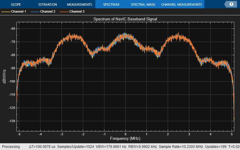
Visualize the NavIC waveform.
if ShowVisualizations
    bbscope = spectrumAnalyzer(SampleRate=fs, ...
    Title="Spectrum of NavIC Baseband Signal", ...
    SpectrumType="power-density", ...
    SpectrumUnits="dBW/Hz");
    bbscope(NavICBBWaveform)
end
Further Exploration
In this example, you generated NavIC SPS data and NavIC complex baseband waveforms for three satellites. Try running this example with these modifications.
Generate NavIC waveforms for more than three satellite, or for a single satellite, as the
PRNIDvariable supports both scalar and vector inputs.This example uses the same random configuration value for all satellites. Update the ephemeris and other properties of the configuration object with real satellite parameters.
Generate a realistic NavIC waveform by enabling the
EnableImpairmentsoption at the start of this example. This option adds Global Navigation Satellite System (GNSS) impairments to the generated waveform. The generated output is a impaired composite waveform, rather than multiple individual waveforms.Set the channel configurations (
SNRdB,sigDelay, andfreqOffset) as vectors to specify the channel parameters corresponding to each satellite.
Supporting Files
This example uses these data and helper files.
HelperGNSSChannel.m— Create GNSS channel object to add impairments in waveformHelperNavICBBWaveform.m— Generate NavIC waveformHelperNavICConfig.m— Create configuration object for NavIC navigation dataHelperNavICDataEncode.m— Encode navigation data into bits from data in configuration object
References
[1] ISRO-IRNSS-ICD-SPS-1.1. Indian Regional Navigation Satellite System Signal in Space ICD for Standard Positioning Service. Indian Space Research Organization (ISRO), Bangalore: August, 2017.
[2] "ISRO-NAVIC-ICD-SPS-L1-1.0. NavIC Signal in Space ICD for Standard Positioning Service in L1 Frequency. Indian Space Research Organization (ISRO), Bangalore: August, 2023.