Build Model of Battery Module with Thermal Effects
This example shows how to create and build a Simscape™ system model of a battery module with thermal effects in Simscape™ Battery™. To create the system model of a battery module, you must first create the Cell and ParallelAssembly objects that comprise the battery module, and then use the buildBattery function.
This figure shows the overall process to create a battery module object in a bottom-up approach:
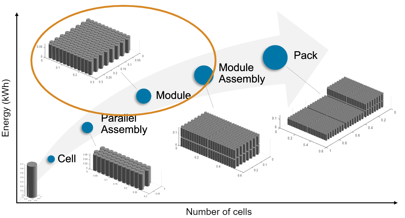
A battery module comprises multiple parallel assemblies. These parallel assemblies, in turn, comprise a number of battery cells connected electrically in parallel under a specific topological configuration or geometrical arrangement.
Once you have created your battery pack object, the buildBattery function creates a library in your working folder that contains a system model block of the battery pack. You can use this system model as a reference in your simulations. The run-time parameters for these models, such as the battery cell impedance or the battery open-circuit voltage, are defined after the model creation and are therefore not covered by the Battery Pack Builder classes. To define the run-time parameters, you can either specify them in the block mask of the generated Simscape models or use the MaskParameters argument of the buildBattery function.
Create Battery Module Object in MATLAB
This section shows how to programmatically generate a battery Module object from the MATLAB® Command Window.
Create Cell Object
To create the battery Module object, first create a Cell object of pouch format.
The PouchGeometry object allows you to define the pouch geometrical arrangement of the battery cell. To create the PouchGeometry object, use the batteryPouchGeometry function and specify the cell height as the first argument, the cell length as the second argument, and the tab location with the name-value argument TabLocation.
pouchGeometry = batteryPouchGeometry(simscape.Value(0.1,"m"),...
    simscape.Value(0.3,"m"),TabLocation="Opposed" );
For more information on the possible geometrical arrangements of a battery cell, see the CylindricalGeometry and PrismaticGeometry documentation pages.
Now use this PouchGeometry object to create a pouch battery cell.
pouchCell = batteryCell(pouchGeometry)
pouchCell =
  Cell with properties:

            Geometry: [1×1 simscape.battery.builder.PouchGeometry]
    CellModelOptions: [1×1 simscape.battery.builder.CellModelBlock]
                Mass: 0.1000 (kg)
            Capacity: 5 (A*hr)
              Energy: 50 (W*hr)

Show all properties
For more information, see the Cell documentation page.
The Cell object allows you to simulate the thermal effects of the battery cell by using a simple 1-D model. To simulate the thermal effects of the battery cell, in the BlockParameters property of the CellModelOptions property of the Cell object, set the ThermalModel property to "LumpedThermalMass".
pouchCell.CellModelOptions.BlockParameters.ThermalModel = "LumpedThermalMass";You can define the thermal boundary conditions for battery parallel assemblies and modules only if you have previously defined a thermal model at the cell level.
Create ParallelAssembly Object
A battery parallel assembly comprises multiple battery cells connected electrically in parallel under a specific topological configuration or geometrical arrangement. In this example, you create a parallel assembly of three pouch cells.
To create the ParallelAssembly object, use the batteryParallelAssembly function. Define the Cell object as the first argument and the number of cells in parallel as the second argument.
parallelAssembly = batteryParallelAssembly(pouchCell,3,...
     ModelResolution="Detailed");
For more information, see the ParallelAssembly documentation page.
Create Module Object
You now have all the foundational elements to create your battery module. A battery module comprises multiple parallel assemblies connected in series. In this example, you create a battery module of 14 parallel assemblies with an intergap between each assembly of 0.005 meters. You also define the model resolution of the module.
To create the Module object, use the batteryModule function. Define the ParallelAssembly object as the first argument and the number of parallel assemblies in series as the second argument. To specify the additional properties, use the name-value arguments InterParallelAssemblyGap and ModelResolution.
module = batteryModule(parallelAssembly,14,...
    InterParallelAssemblyGap=simscape.Value(0.005,"m"), ...
    ModelResolution="Detailed");
For more information, see the Module documentation page.
Define Thermal Boundary Conditions
For your Module object, you can define the thermal paths to the ambient, the coolant, and the location of the cooling plate by using the AmbientThermalPath, CoolantThermalPath, and CoolingPlate properties.
Define Ambient Thermal Path
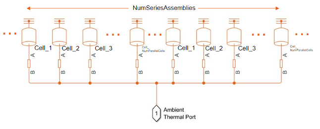
To define a thermal path to ambient, set the AmbientThermalPath property to "CellBasedThermalResistance". Setting this property automatically propagates its value to all the subcomponent battery objects inside this Module object. However, this change does not propagate to the other battery objects in your MATLAB workspace.
module.AmbientThermalPath = "CellBasedThermalResistance";This command adds and connects one Thermal Resistor block to every thermal port in a cell model. The other thermal ports from all resistors connect to a single thermal node. You can then connect this thermal node with a constant temperature source or other blocks in the Simscape libraries.
Define Coolant Thermal Path
To define a thermal path from cells to the coolant, set the CoolantThermalPath property to "CellBasedThermalResistance". Setting this property automatically propagates its value to all the subcomponent battery objects inside this Module object. However, this change does not propagate to the other battery objects in your MATLAB workspace.
module.CoolantThermalPath = "CellBasedThermalResistance";This command adds and connects one Thermal Resistor block to every thermal port in a cell model. The other thermal ports from all resistors connect to a single thermal node. You can then connect this thermal node with a constant temperature source or other blocks in the Simscape libraries. You can individually parameterize every thermal resistance with a different value.
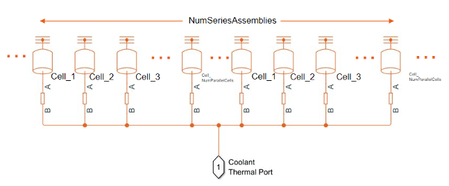
You can use the Thermal Resistor block to capture the conduction resistance relative to the cell, the thermal interface materials, and other materials along the path to the coolant. If you define a cooling system such as a cooling plate for the battery module, the other thermal port of the Thermal Resistor block is connected to an array of thermal nodes connector.
Define Cooling Plate Location
To define the location of the cooling plate on your battery module, set the CoolingPlate property to either "Top" or "Bottom". Setting this property automatically propagates its value to all the subcomponent battery objects inside this Module object. However, this change does not propagate to the other battery objects in your MATLAB workspace.
module.CoolingPlate = "Bottom";This command connects every thermal node of each cell model in your battery module to a corresponding element inside an array of thermal nodes connector. If you also enable the CoolantThermalPath, then the software adds a thermal resistance between each battery model and its corresponding element inside the array of thermal nodes.
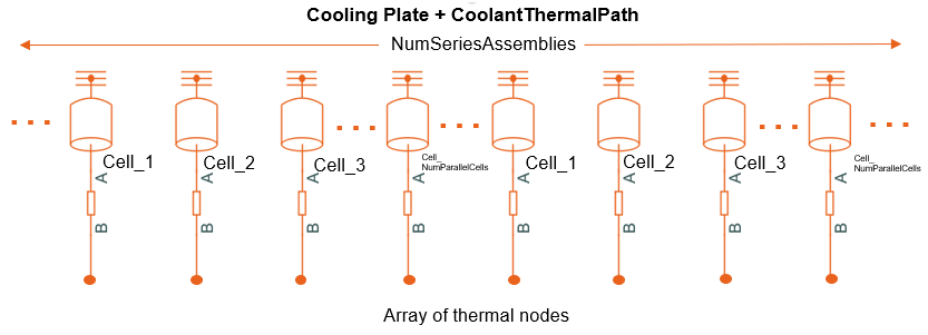
The array of thermal nodes is exposed at the module level as a single connector but is multi-dimensional. You can connect an array of thermal nodes only to another array of thermal nodes of the same size. You can add a Cooling Plate block from the Simscape Battery library as heat sink.
To facilitate multi-dimensional thermal domain connections, you can use the ThermalNodes property of your Module object as input to the Cooling Plate block. You can view the number of thermal nodes, dimensions, and locations of the thermal nodes of the underlying cell models by accessing the ThermalNodes property.
disp(module.ThermalNodes);
       Top: [1×1 struct]
    Bottom: [1×1 struct]
Visualize Battery Module and Check Model Resolution
To obtain the number of Simscape Battery Battery Equivalent Circuit blocks used for the pack simulation, use the NumModels property of your Module object.
disp(module.NumModels);
42
To visualize the battery module before you build the system model and to view its model resolution, create the figure where you want to visualize your module and then use the batteryChart function. To view the model resolution of the module, define the name-value argument SimulationStrategyVisible as "On".
f = figure(Color="w",Position=[0,0,1000,500]);
tl = tiledlayout(1,2,"Parent",f);
nexttile(tl)
moduleChart1 = batteryChart(tl,module);
nexttile(tl)
moduleChart2 = batteryChart(tl,module,SimulationStrategyVisible="On");
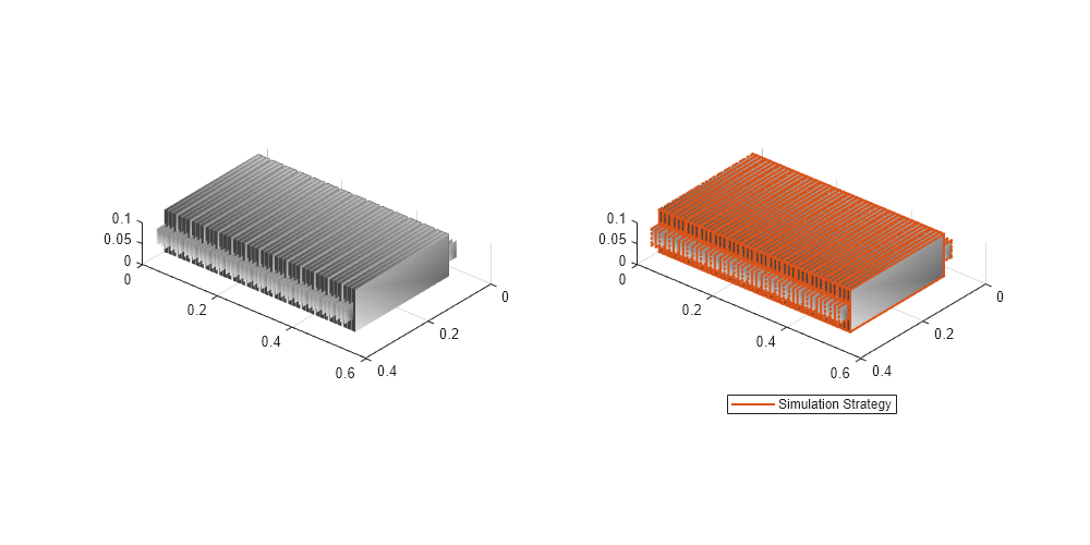
For more information, see the batteryChart documentation page.
Build Simscape Model for the Battery Module Object
After you have created your battery objects, you need to convert them into Simscape models to use them in block diagrams. You can then use these models as reference for your system integration and requirement evaluation, cooling system design, control strategy development, hardware-in-the-loop, and many more applications.
To create a library that contains the Simscape Battery model of the Module object you created in this example, use the buildBattery function.
buildBattery(module,LibraryName="moduleBTMSExample",Verbose="off");
This function creates a library named moduleBTMSExample_lib in your working directory. This library contains the Simscape models of your Module and ParallelAssembly objects.
To build a more detailed model of a battery pack, see the Build Detailed Model of Battery Pack from Pouch Cells example.
For an application of a battery thermal effects model with a coolant thermal path, see the Protect Battery During Charge and Discharge for Electric Vehicle example.
Explore Battery Module and Build Model in Battery Builder App
In this example, you programmatically created the battery module and all its subcomponents by calling the relevant objects and functions in the MATLAB Command Window. Alternatively, if you prefer a more interactive and visual approach, you can use the Battery Builder app. Using this app, you can interactively import existing battery objects or build them from scratch, explore and edit properties, and view the battery hierarchy and 3-D visualization. You can then build the Simscape system model of your objects and use it as a reference in your simulations. You can also export the objects in your workspace. To learn how to use the Battery Builder app to generate battery objects and build Simscape models, see the Get Started with Battery Builder App example.
Explore the battery module that you created in this example. Open the Battery Builder app. On the Apps tab, under Simscape, click the Battery Builder icon. Alternatively, you can open the app from the command line:
batteryBuilder
Import the battery pack object from the moduleBTMSExample MAT file. Under the Battery Builder tab, in the Import section of the toolstrip, click Import. Then click Import from MAT-file and load the moduleBTMSExample MAT file.
The Battery Builder app now comprises a Module object and each of its subcomponents.
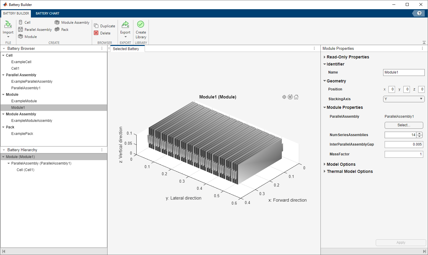
The Battery Browser panel on the left of the app contains all the battery objects in the current active session of the app. You can select an object, visualize it in the Selected Battery tab, check its hierarchy and child objects in the Battery Hierarchy panel, and edit its properties in the Properties panel on the right of the app.
You can edit properties of the plot under the Battery Chart tab, such as the axes labels, axes direction, title of the plot, and lights. You can also check the current simulation strategy and model resolution of the selected battery object. To visualize the simulation strategy in the plot, in the Simulation Strategy section of the toolstrip, check the Visible box.
Finally, if you modified your battery object and you want to create a library model of the updated Module object, under the Battery Builder tab, in the Library section of the toolstrip, click Create Library. In the new window, specify the folder in which you want to save the library, the library name, and whether to use numeric values or variable names for the mask parameters and mask initial targets.

Click Create Library to generate the updated library model of your battery object in the specified folder. Open this model to access your battery objects as Simscape blocks that you can use as a starting point for architecture evaluation in early development stages, software and hardware development, system integration and requirement evaluation, cooling system design, control strategy development, hardware-in-the-loop, and many more applications.