Average-Value DC-DC Converter
R2026bAverage-value DC-DC converter
Average-Value DC-DC Converter block
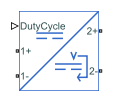
To add a block to a model, double-click the canvas and start typing the block name. Then, select the block from the list.
Libraries:
Simscape /
Electrical /
Semiconductors & Converters /
Converters
Description
The Average-Value DC-DC Converter block represents a controlled DC-DC converter. You can model a buck, boost, or noninverting buck-boost converter. The block excludes switching events and uses a simple power balance to relate the converter output to the duty cycle, voltage reference, or current reference. This simplicity allows rapid simulation. Use this block for system-level applications such as designing outer-loop controllers or optimizing systems in which you deploy power electronics.
The Average-Value DC-DC Converter block supports two
implementation modes. The behavioral model is simpler and does not include energy
storage dynamics. You specify the efficiency, either as a constant value or as a
function of output current. The average-value model uses a modification to the
behavioral model which includes LC dynamics. You specify the inductance, inductor series
resistance, capacitance, and capacitor effective series resistance. Losses arise from
the inductor series resistance, capacitor effective series resistance, and the loading.
Efficiency is an emergent result of these parasitics and the operating point. To control
the inverter state variables, set the Implementation mode parameter
to Average value. For fast simulation, set this parameter to
Behavioral.
Behavioral Model
If you set the Control input parameter to Duty
cycle, the input current and output voltage are functions of the
duty cycle and efficiency. The voltage and current also depend on the converter
type. The block enforces the ideal voltage transfer ratio for the selected
topology.
This diagram shows the equivalent circuit for the ideal core of an average-value DC-DC converter. This ideal core is equivalent to the behavioral model with a duty cycle input and 100% efficiency. The circuit contains a controlled current source and a controlled voltage source.
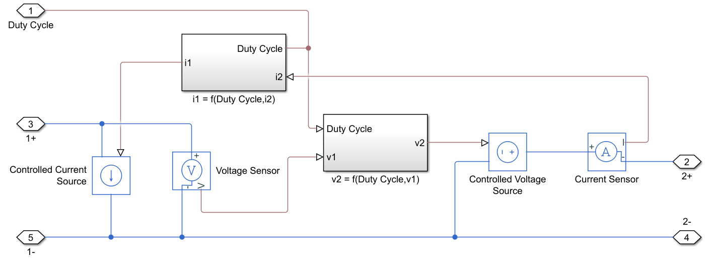
This table shows the output voltage, v2, and input current, i1 of the ideal converter core. The output voltage and input current are functions of the input voltage, v1, and output current, i2, respectively.
Voltage and Current Equations
| Converter Type | Output Voltage, | Input Current, |
|---|---|---|
| Buck | ||
| Boost | ||
| Buck-Boost |
If the efficiency is less than 100%, the Average-Value DC-DC Converter block scales the input current accordingly.
If you set the Control input parameter to
Current reference, the converter sets the output
current and it computes the voltage. Similarly, if you set the Control
input parameter to Voltage reference, the
converter sets the output voltage and it computes the current.
Average-Value Model
Since R2025a
The average-value implementation uses the same ideal converter core as the behavioral implementation but with additional external Inductor and Resistor blocks from the Simscape™ Foundation library.
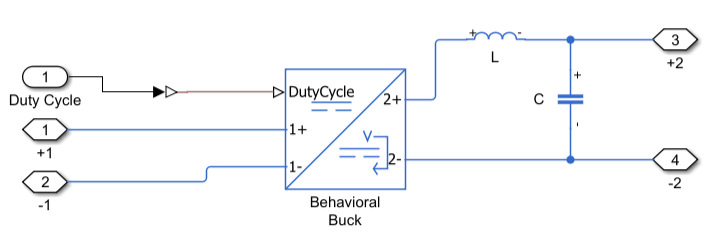
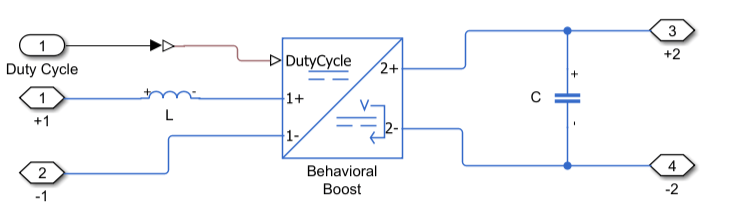
The diagrams below show the equivalent circuit for each converter topology. The ideal core represents the switches and diodes that you want to average the behavior of. The inductor and capacitor operate as they do in the switching converters. The Average-Value DC-DC Converter blocks in these diagrams, represent the ideal converter core, and have these parameter values:
Implementation mode is
Behavioral.Control input is
Duty cycle.Converter efficiency is
Constant.Efficiency (%) is
100.
This figure shows the equivalent circuit of an average-value model of a buck converter. The average-value model is equivalent to the behavioral model of a buck converter with an LC filter on output side.
This figure shows the equivalent circuit of an average-value model of a boost converter. The average-value model is equivalent to the behavioral model of a boost converter with an inductor connected to the positive input and a capacitor across the output..
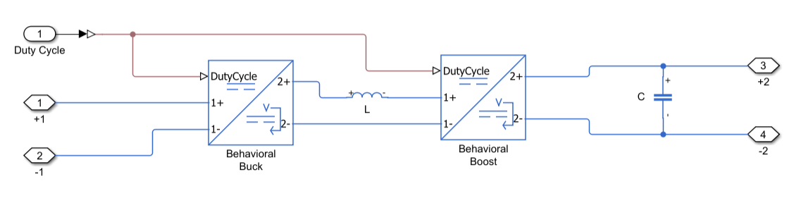
This figure shows the equivalent circuit of an average-value model of a buck-boost converter. The average-value model uses two behavioral models in stages. The stages share the duty cycle control signal. The converter core on the input side is a buck converter and the converter core on the output side is a boost converter. The inductor connects between the two stages, from the positive output of the buck converter to the positive input of the boost converter. The capacitor connects across the output of the second stage.
Variables
Since R2025a
To enable the Initial Targets and Nominal
Values sections, set the Implementation mode
parameter to Average value.
To set the priority and initial target values for the block variables before simulation, use the Initial Targets section in the block dialog box or Property Inspector. For more information, see Set Priority and Initial Target for Block Variables.
Nominal values provide a way to specify the expected magnitude of a variable in a model. Using system scaling based on nominal values increases the simulation robustness. You can specify nominal values using different sources, including the Nominal Values section in the block dialog box or Property Inspector. For more information, see System Scaling by Nominal Values.
Examples
Average-Value DC-DC Converter Control
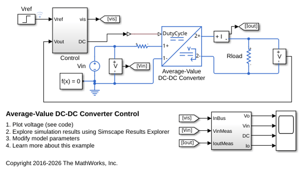
Control the output voltage of a buck-boost converter. To adjust the duty cycle, the Control subsystem uses a PI-based control algorithm. An average-value DC-DC converter model is used to speed up the simulation. The input voltage and the system load are held constant throughout the simulation. The total simulation time (t) is 0.25 s. At t = 0.15 s, the voltage reference changes and the system switches from buck mode to boost mode.
Linearize DC-DC Converter Model
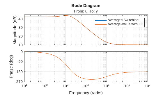
Linearize a model of a DC-DC converter using averaged switching or an average-value converter.
Assumptions and Limitations
The Average-Value DC-DC Converter block expects a positive input voltage. If the input voltage is negative, this block limits the voltage to 0 and throws a warning. (since R2026b)
Before R2026b: The input voltage must be positive. If the input voltage is negative, this block throws an error.
All converter types use the same polarity for input and output.
Ports
Conserving
Parameters
Extended Capabilities
Version History
Introduced in R2018bSee Also
Simscape Blocks
- Average-Value Chopper | Average-Value Inverter (Three-Phase) | Average-Value Rectifier (Three-Phase) | Bidirectional DC-DC Converter | Buck Converter | Buck-Boost Converter | Boost Converter | Converter (Three-Phase) | DC-DC Converter | Rectifier (Three-Phase) | Three-Level Converter (Three-Phase)

