Two-Winding Transformer (Three-Phase)
R2026bThree-phase linear nonideal wye- and delta-configurable two-winding transformer with saturation capability
Two-Winding Transformer (Three-Phase) block
To add a block to a model, double-click the canvas and start typing the block name. Then, select the block from the list.
Libraries:
Simscape /
Electrical /
Passive /
Transformers
Description
The Two-Winding Transformer (Three-Phase) block represents a linear nonideal three-phase two-winding transformer that transfers electrical energy between two or more circuits through electromagnetic induction. The block includes linear winding leakage and linear core magnetization effects.
You can parameterize the block using equivalent-circuit impedances or positive-sequence and zero-sequence test data (since R2026b).
The configuration options for both the primary and secondary windings are:
Wye with floating neutral — Star or T configuration with Floating Neutral (Three-Phase)
Wye with neutral port — Star or T configuration with Neutral Port (Three-Phase)
Wye with grounded neutral — Star or T configuration with Grounded Neutral (Three-Phase)
Delta 1 o'clock — Mesh configuration with a lagging 30 degree phase shift relative to the voltage of a connected wye configuration
Delta 11 o'clock — Mesh configuration with leading 30 degree phase shift relative to the voltage of a connected wye configuration
If you parameterize the block using circuit impedances, you can specify the core type as one of these options:
Three-phase five-limb
Three-phase
							three-limb
Although a three-limb core is typically less expensive, a five-limb core offers these advantages:
Lower impedance for the zero-sequence component of current, that is between the line and neutral, in the case of an unbalanced load
Greater heat dissipation
Equations
This block is implemented in the magnetic domain using basic magnetic reluctances, windings, and eddy currents blocks.
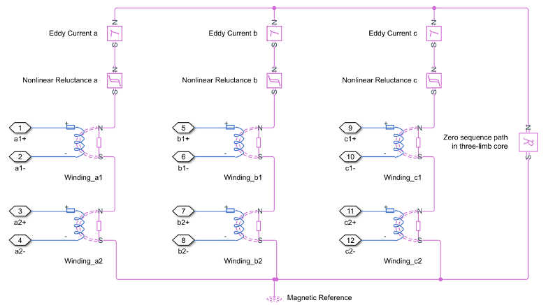
It is important to determine the relation between the electrical domain parameters from the block mask and the magnetic domain parameters used in the model:
n1 is the number of the primary winding turns.
n2 is the number of the secondary winding turns.
Lm is the shunt magnetizing inductance.
L0 is the zero-sequence inductance.
Lp is the primary winding leakage inductance.
Ls is the secondary winding leakage inductance.
Rm is the shunt magnetizing resistance.
R is the magnetizing reluctance between phases.
R0 is the zero sequence reluctance.
Rl1 is the primary winding leakage reluctance.
Rl2 is the secondary winding leakage reluctance.
Leddy is the conductance of eddy current loop
For two-winding transformers (three-phase), the coupling between different windings in each phase is identical.
In the case of a five-limb transformer, the extra magnetic flux paths provided by the extra limbs can be represented by zero sequence reluctances, which are originally designed for magnetic paths through the air in the three-limb transformer.
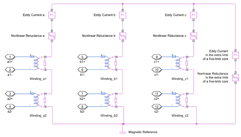
In a five-limb model, the magnetic reluctances from the phases to the extra limbs are supposed to be equal to the magnetic reluctances between phases.
Therefore:
When you set the Specify parameterization by parameter to
Test data, the block must derive the
equivalent-circuit parameters from the measured test data.
The test data specifies the electrical quantities that you obtain from standard transformer tests, such as no-load and short-circuit tests. From these values, the block computes the corresponding equivalent-circuit impedances that characterize the transformer behavior under both positive‑sequence and zero‑sequence conditions.
For the positive-sequence equivalent circuit, the block defines the relationships between the test data and the equivalent parameters by using these mathematical expressions:
where:
Xl1 is the per-unit primary leakage reactance.
Xl2 is the per-unit secondary leakage reactance.
X121 is the per-unit positive-sequence short-circuit reactance.
P1 is the per-unit positive-sequence no-load loss.
Iext1 is the per-unit positive-sequence no-load excitation current.
R1 is the per-unit primary winding resistance.
The block calculates the shunt magnetizing resistance, Rm, from the specified positive-sequence core resistive loss, P1core:
The block then derives the shunt magnetizing reactance, Xm from the no-load excitation current using the calculated shunt magnetizing resistance and impedance relationship:
Xm and Rm defines the shunt magnetizing branch of the positive-sequence equivalent circuit.
For the zero-sequence equivalent circuit, the block calculates the open-circuit impedance Zopen and the short-circuit impedance Zshort using the zero-sequence no-load and short-circuit test data,
where:
X0 is the per-unit zero-sequence reactance.
R0 is the per-unit zero-sequence resistance.
R2 is the per-unit secondary winding resistance.
By separating the real and imaginary components of these impedances, the block calculates the zero-sequence resistance and reactance,
where:
X120 is the per-unit zero-sequence short-circuit reactance-
Iext0 is the per-unit zero-sequence no-load excitation current.
P0 is the per-unit zero-sequence no-load loss.
These quantities characterize the transformer behavior under zero‑sequence excitation and model the zero‑sequence losses and leakage effects.
Generate Derived Data Sheet
Since R2026b
You can generate a derived data sheet for the Two-Winding Transformer (Three-Phase) block that contains summary tables and characteristic plots similar to those that device manufacturers provide in their data sheets. A built-in MATLAB® script calculates the block-level characteristics based on the parameter values in your model. Use derived data sheets to explore the effect of your parameter choices on device characteristics, help you select manufactured parts, or share your component-level design with others.
The derived data sheet for the Two-Winding Transformer (Three-Phase) block includes these plots:
Open-circuit test results — Secondary voltage versus excitation current
Short-circuit test results — Current versus phase voltage
Load test results — Voltage regulation and efficiency versus load
Iron loss, copper loss, and total loss versus load
To generate a derived data sheet:
Open the MATLAB script by clicking the Open live script button next to the Derived data sheet parameter in the Utilities section of the block dialog box.
Click the Generate Data Sheet button in the script.
For more information about derived data sheets, see Generate Derived Data Sheets.
Display Options
You can display the transformer per-unit base values in the MATLAB command window. To display the transformer values, in the Utilities section, click the Display button next to the Base values parameter.
Variables
To set the priority and initial target values for the block variables before simulation, use the Initial Targets section in the block dialog box or Property Inspector. For more information, see Set Priority and Initial Target for Block Variables.
Nominal values provide a way to specify the expected magnitude of a variable in a model. Using system scaling based on nominal values increases the simulation robustness. You can specify nominal values using different sources, including the Nominal Values section in the block dialog box or Property Inspector. For more information, see System Scaling by Nominal Values.
Examples
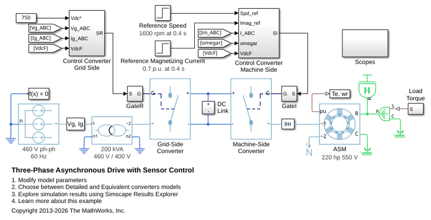
Three-Phase Asynchronous Drive with Sensor Control
Control and analyze the operation of an Asynchronous Machine (ASM) using sensored rotor field-oriented control. The model shows the main electrical circuit, with three additional subsystems containing the controls, measurements, and scopes. The Controls subsystem contains two controllers: one for the Grid-Side Converter (AC/DC) and one for the Machine-Side Converter (DC/AC). The Scopes subsystem contains two time scopes: one for the Grid-Side Converter and one for the ASM. When the model is executed, a Spectrum Analyzer opens and displays frequency data for the A-Phase Supply Current.
Three-Phase Asynchronous Drive with Sensorless Control
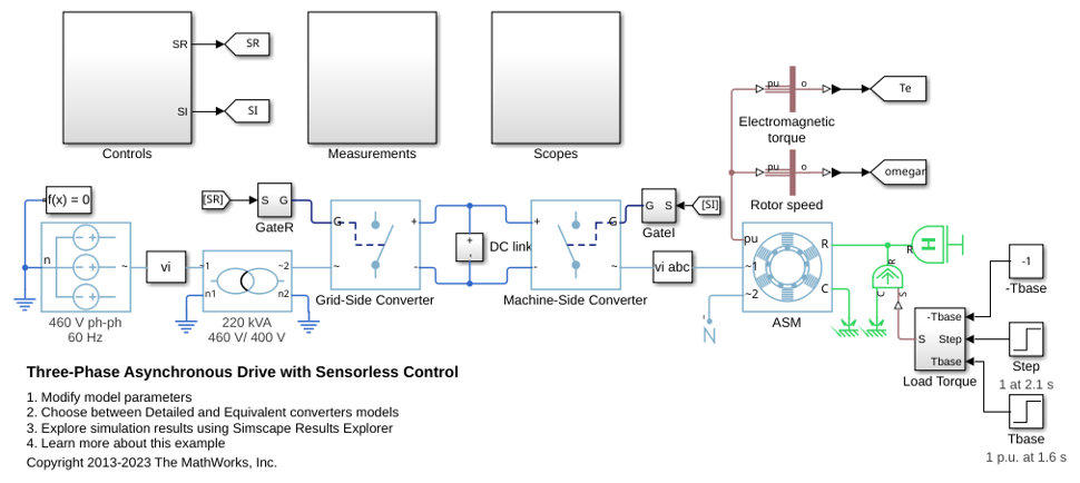
Control and analyze the operation of an Asynchronous Machine (ASM) using sensorless rotor field-oriented control. The model shows the main electrical circuit, with three additional subsystems containing the controls, measurements, and scopes. The Controls subsystem contains two controllers: one for the Grid-Side Converter (AC/DC) and one for the Machine-Side Converter (DC/AC). The Scopes subsystem contains two time scopes: one for the Grid-Side Converter and one for the ASM. When the model is executed, a Spectrum Analyzer opens and displays frequency data for the A-Phase Supply Current.
Three-Phase Bridge Cycloconverter
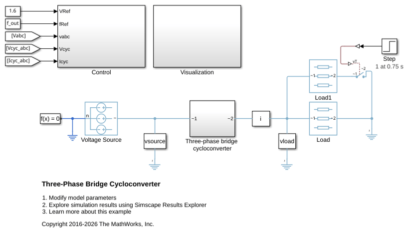
A three-phase bridge cycloconverter. The cycloconverter consists of 36 thyristors and has the capacity to lower the frequency of the input voltage. The Control subsystem implements the cycloconverter RMS voltage control. It also provides pulse generation for the firing of the thyristors. The Visualization subsystem contains scopes that allow you to see the simulation results. The simulation time, t, is 1 second. The load increases when Load1 switches on at t = 0.75 seconds.
Model Transmission System Using Delta Reference (Three-Phase) Block
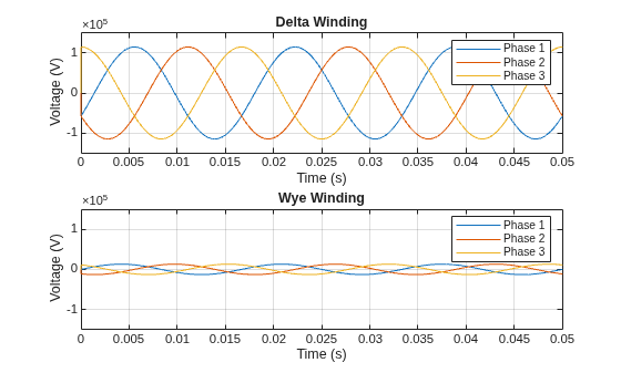
Use a Delta Reference (Three-Phase) block to provide a reference point for delta winding in a simple model of a transmission system.
IEEE 9-Bus System
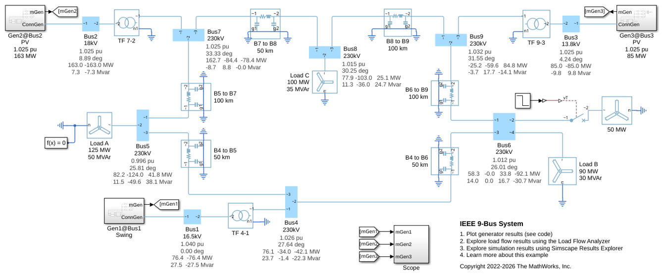
Model a 9-bus three-phase power system network. This example is based on the IEEE® benchmark test case. For more information, see "Power System Control and Stability" by P. M. Anderson and A. A. Fouad (IEEE Press, 2003).

